Epson BrightLink 595Wi Installation Guide - Page 49
adjustment. If other objects are on the projected image, angle adjustment may not
 |
View all Epson BrightLink 595Wi manuals
Add to My Manuals
Save this manual to your list of manuals |
Page 49 highlights
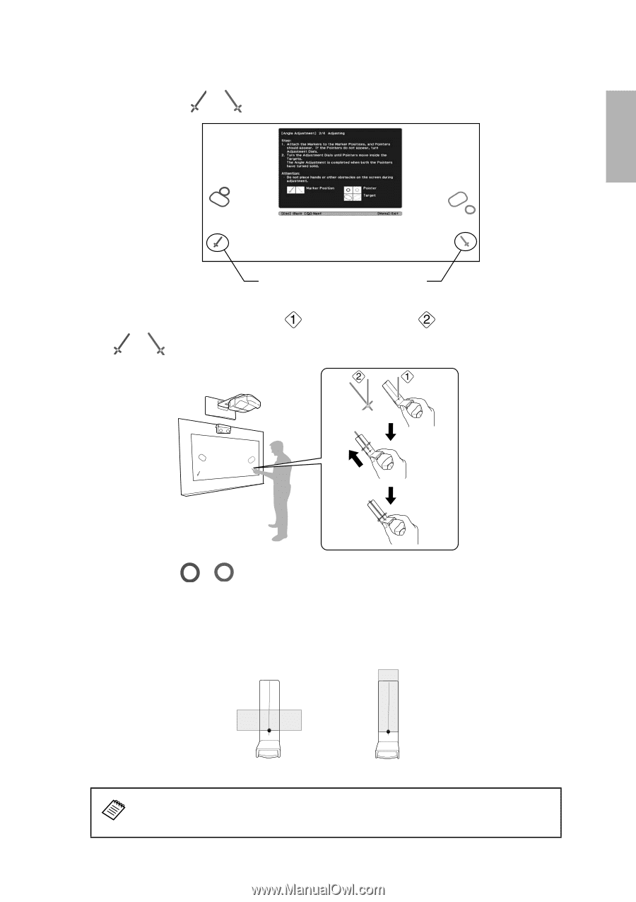
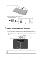
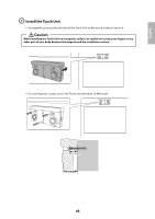
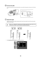
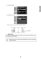
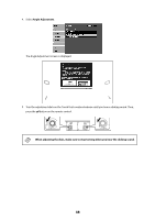
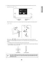
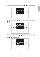
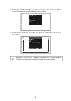
English 6. Attach the two markers you removed from the Touch Unit to the marker positions shown on the projected screen ( ) ( ). Blue marker position Green marker position Match the positions so that the crosses ( ) overlap with the points ( ) on the marker positions ( ) ( ). When pointers ( ) ( ) with the same color (blue and green) as the marker positions are displayed on the left and right of the projection screen, attach the markers to the projection screen as follows: • For magnetic screens: Place the bottom of the markers onto the screen. • For non-magnetic screens: Use the supplied tape to secure the markers. Attach the tape so that each end of the marker is secure on the screen. Correct position Incorrect position Do not place anything other than the markers near the projected image during angle adjustment. If other objects are on the projected image, angle adjustment may not be performed correctly. 49
-
 1
1 -
2
-
3
-
4
-
5
-
6
-
7
-
8
-
9
-
10
-
11
-
12
-
13
-
14
-
15
-
16
-
17
-
18
-
19
-
20
-
21
-
22
-
23
-
24
-
25
-
26
-
27
-
28
-
29
-
30
-
31
-
32
-
33
-
34
-
35
-
36
-
37
-
38
-
39
-
40
-
41
-
42
-
43
-
 44
44 -
 45
45 -
 46
46 -
 47
47 -
 48
48 -
 49
49 -
 50
50 -
 51
51 -
 52
52 -
 53
53 -
 54
54 -
55
-
56
-
57
-
58
-
59
-
60
-
61
-
62
-
63
-
64
-
65
-
66
-
67
-
68
-
69
-
70
-
71
-
72
-
73
-
74
-
75
-
76
-
77
-
78
-
79
-
80
-
81
-
82
-
83
-
84
-
85
-
86
-
87
-
88
-
89
-
90
-
91
-
92
-
93
-
94
-
95
-
96
-
97
-
98
-
99
-
100
-
101
-
102
-
103
-
104
-
105
-
106
-
107
-
108
-
109
-
110
-
111
-
112
-
113
-
114
-
115
-
116
 |
 |