Epson BrightLink 697Ui Installation Guide - Control Pad and Touch Unit - Page 35
Do not place anything other than the markers near the projected image during angle
 |
View all Epson BrightLink 697Ui manuals
Add to My Manuals
Save this manual to your list of manuals |
Page 35 highlights
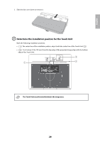
7. Attach the two markers to the positions shown on the projected screen ( ) ( ). Blue marker position Green marker position Match the positions so that the crosses ( ) overlap with the points ( ) on the marker positions ( ) ( ). Move the marker over the projected cross until the lines of the cross align with the lines on the marker. When circles with the same color (blue and green) as the marker positions are displayed on the left and right of the projection screen, attach the markers to the projection screen as follows: • For magnetic screens: Place the bottom of the markers onto the screen. • For non-magnetic screens: Use the supplied tape to secure the markers. Make sure that both ends of the markers are flush with the screen. Correct position Incorrect position Do not place anything other than the markers near the projected image during angle adjustment. If other objects are on the projected image, angle adjustment may not be performed correctly. 34
-
 1
1 -
2
-
3
-
4
-
5
-
6
-
7
-
8
-
9
-
10
-
11
-
12
-
13
-
14
-
15
-
16
-
17
-
18
-
19
-
20
-
21
-
22
-
23
-
24
-
25
-
26
-
27
-
28
-
29
-
 30
30 -
 31
31 -
 32
32 -
 33
33 -
 34
34 -
 35
35 -
 36
36 -
 37
37 -
 38
38 -
 39
39 -
 40
40 -
41
-
42
-
43
-
44
-
45
-
46
-
47
-
48
-
49
-
50
-
51
-
52
-
53
-
54
-
55
-
56
-
57
-
58
-
59
-
60
-
61
-
62
-
63
-
64
-
65
-
66
-
67
-
68
-
69
-
70
-
71
-
72
-
73
-
74
-
75
-
76
-
77
-
78
-
79
-
80
-
81
-
82
-
83
-
84
-
85
-
86
-
87
-
88
-
89
-
90
 |
 |
