Epson FX-1050 Product Information Guide - Page 5
FX - 850/1050 DOT - MATRIX PRINTER, Interface Specifications - manual
 |
View all Epson FX-1050 manuals
Add to My Manuals
Save this manual to your list of manuals |
Page 5 highlights
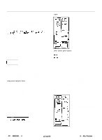
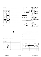
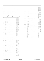
FX - 850/1050 DOT - MATRIX PRINTER SelecType The settings you select using the SelecType panel remain valid even after you turn off, reset, or initialize the printer. FONT Press this button to select draft, near letter quality Roman. or near letter quality Sans Serif. The indicator light shows which font has been selected. CHARACTERS PER INCH Press this button to select the characters per inch (cpi). You can choose 10 CPI. 12 CPI. or PS (proportional spacing). The indicator light shows the selected character spacing. CONDENSED Press this button to select either condensed or normal printing. The light is on when the printer is in condensed mode. In this mode, all characters are approximately 60% of their normal width. Note: Proportional spacing and condensed mode cannot be combined. If you select both, only proportional spacing works. 1 Interface Specifications 1 Your printer is equipped with an &bit parallel interface. For specifications for optional interfaces, see the manuals provided with the optional interfaces. Pin assignments for the parallel interface Connector pin assignments and a description of their respective interface signals are shown in the following table. Signal Pin 1 Return Pin Signal 19 STROBE 1 I I Direc- tion Description IN STROBE pulse lo read data in. Pulse width must be more than 0.5 microseconds at the receiving terminal IN These signals represent information of IN the 1st to 8th bits of parallel data IN respectively Each signal is at HIGH level IN when data is logical 1 and LOW when it is IN logical 0 IN 1: OUT About a 12-microsecond pulse LOW indicates that data has been received I I and that the printer is ready lo accept more data l The column heading "Direction" refers to the direction of signal flow as viewed from the printer. . "Return" denotes the twisted-pair return. to be connected at signal ground level. For the interface wiring, be sure to use a twisted-pair cable for each signal and to complete the connection on the return side. These cables should be shielded and connected to the chassis of the host computer and the printer. l All interface conditions are based on TTL level. Both the rise and the fall times of each signal must be less than 0.2 microseconds. l Data transfer must be carried out by observing the ACKNLG or BUSY signal. Data transfer to this printer can be carried out only after receipt of the ACKNLG signal or when the level of the BUSY signal is LOW. Printing enabled/disabled signals and control conditions The following table shows the relationship between printing being enabled or disabled, the on line/off line status, and the receipt of the data on/off control characters, DC1 or DC3. ON LINE SLCT IN DC1/DC3 ERROR (Indicator on/off control) BUSY ACKNLG 1 Printing (Disabled/ enabled) I 1 on line on line off line interface) High DC1 Recv'd High High DC3 Recv'd High High/Low DC1/DC3 Low (no effect) (no effect) cond.) High/Low Pulsed Enabled ea. char. High/Low Pulsed Disabled' ea. char. High Not Disabled generated *While printing is disabled, character data is being received and acknowledged so that the printer can look for another DC1 character, which would allow it to resume printing. 9 - Pin Printers 12/12/88 FX-850/1050-5
-
 1
1 -
 2
2 -
 3
3 -
 4
4 -
 5
5 -
 6
6 -
 7
7 -
 8
8
 |
 |
