Epson FX-86e User Manual - Page 154
Serial Interface Settings, by one or two groups of DIP switches located on the serial interface
 |
View all Epson FX-86e manuals
Add to My Manuals
Save this manual to your list of manuals |
Page 154 highlights
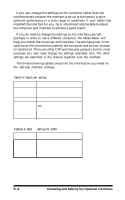
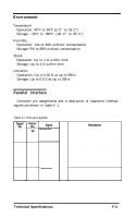
4. Insert the interface board beneath the printer mechanism, as indicated by the lines in Figure E-5, and plug it into the connector marked CN2 on the main circuit board of the printer. Figure E-5. Inserting the board Figure E-6. I Connecting frame ground wire 5. Secure the board to the three supports using the screws provided. 6. Connect the frame ground wire to the FG terminal tag on the interface board, as shown in Figure E-6. 7. Reassemble the printer, reversing the procedure described in the previous section. Serial Interface Settings If you are using an optional serial interface, you may need to change the communications protocol of the printer or the computer for them to communicate properly. The protocol used by the printer is decided by one or two groups of DIP switches located on the serial interface board; the protocol used by the computer can probably be altered by a software command. It is essential that the printer and computer use compatible protocols. Choosing and Setting Up Optional Interfaces E.7
-
 1
1 -
2
-
3
-
4
-
5
-
6
-
7
-
8
-
9
-
10
-
11
-
12
-
13
-
14
-
15
-
16
-
17
-
18
-
19
-
20
-
21
-
22
-
23
-
24
-
25
-
26
-
27
-
28
-
29
-
30
-
31
-
32
-
33
-
34
-
35
-
36
-
37
-
38
-
39
-
40
-
41
-
42
-
43
-
44
-
45
-
46
-
47
-
48
-
49
-
50
-
51
-
52
-
53
-
54
-
55
-
56
-
57
-
58
-
59
-
60
-
61
-
62
-
63
-
64
-
65
-
66
-
67
-
68
-
69
-
70
-
71
-
72
-
73
-
74
-
75
-
76
-
77
-
78
-
79
-
80
-
81
-
82
-
83
-
84
-
85
-
86
-
87
-
88
-
89
-
90
-
91
-
92
-
93
-
94
-
95
-
96
-
97
-
98
-
99
-
100
-
101
-
102
-
103
-
104
-
105
-
106
-
107
-
108
-
109
-
110
-
111
-
112
-
113
-
114
-
115
-
116
-
117
-
118
-
119
-
120
-
121
-
122
-
123
-
124
-
125
-
126
-
127
-
128
-
129
-
130
-
131
-
132
-
133
-
134
-
135
-
136
-
137
-
138
-
139
-
140
-
141
-
142
-
143
-
144
-
145
-
146
-
147
-
148
-
 149
149 -
 150
150 -
 151
151 -
 152
152 -
 153
153 -
 154
154 -
 155
155 -
 156
156 -
 157
157 -
 158
158 -
 159
159 -
160
-
161
-
162
-
163
-
164
-
165
-
166
-
167
-
168
-
169
-
170
-
171
-
172
-
173
 |
 |
