Eureka AirSpeed ONE AS2001TIS Quick Start Guide - Page 1
Eureka AirSpeed ONE AS2001TIS Manual
 |
View all Eureka AirSpeed ONE AS2001TIS manuals
Add to My Manuals
Save this manual to your list of manuals |
Page 1 highlights
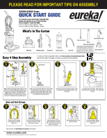
PLEASE READ FOR IMPORTANT TIPS ON ASSEMBLY AS2000-AS2039 Series QUICK START GUIDE For detailed vacuum information including FAQs please visit eureka.com or call the Customer Service Helpline: 1-800-282-2886. 8 a.m. to 7:30 p.m. (CST), Monday - Friday 10 a.m. to 6:30 p.m. (CST), Saturday - Sunday What's In The Carton Base (A) Backbone (B) Handle (C) Dust Cup (D) Hose (E) Crevice Tool (F) Dusting Brush (H) Extension Wand (G) Note: Remove Crevice Tool (F) and Extension Wand (G) from inside of Backbone (B) hole before assembly. Turbo Nozzle (I) Easy 4 Step Assembly To view our "How to Assemble" demo, visit www.eureka.com/airspeed/assembly, scan the QR code to the right, or contact our customer service helpline. STEP 1 Fig. 1 Alternate View B STEP 2 A B A Hose Retainer C STEP 3 STEP 4 Fig. 2 B B A Fig 1: With the backbone (B) loosely on the base (A), rotate the backbone forward until the vaccum is locked in the upright position. Fig 2: stand as shown and push down on backbone (B) valve to snap into place. Pull up to ensure the backbone has locked properly. Align so that the hose retainer on the handle (C) is facing the vacuum front. Lower the handle (C) onto the backbone (B). Push down to snap into place. Pull up to ensure the handle has locked properly. Put dust cup (D) into place on base. Push cup handle toward backbone (B) to snap into place. To attach hose connector, align tabs and lower hose onto connector. Turn clockwise to lock. Hose and Tool Storage STEP 1 E Hose Retainer STEP 2 C E Route hose (E) through hose retainer on front of handle (C). Put hose end (E) into hook at base of tool clips. Then push hose into clips. See reverse for Get Ready to Vacuum instructions www.eureka.com © 2013 Electrolux Home Care Products, Inc. Printed in China PN 87469 STEP 3 G STEP 4 H STEP 5 I Slide crevice tool (F) into top of extension wand end (G). Place into clips on the side of the vacuum. Store dusting brush (H) on back of vacuum. On some models: Attach turbo nozzle (I) to clip on handle (C).
-
 1
1 -
 2
2
 |
 |
