Fluke 8808A User Manual
Fluke 8808A Manual
 |
View all Fluke 8808A manuals
Add to My Manuals
Save this manual to your list of manuals |
Fluke 8808A manual content summary:
- Fluke 8808A | User Manual - Page 1
® 8808A Digital Multimeter Users Manual July 2007 © 2007 Fluke Corporation, All rights reserved. All product names are trademarks of their respective companies. - Fluke 8808A | User Manual - Page 2
its functional specifications for 90 days and that it has been properly recorded on non-defective media. Fluke does not warrant that software will be error free or operate without interruption. Fluke authorized resellers shall extend this warranty on new and unused products to end-user customers - Fluke 8808A | User Manual - Page 3
Environment 1-8 Safety...1-8 EMC ...1-8 Triggering ...1-8 Math Functions 1-8 Electrical...1-9 Remote Interfaces 1-9 Warranty ...1-9 Electrical Specifications 1-9 DC Voltage Specifications 1-9 AC Voltage Specifications 1-10 Resistance ...1-11 DC Current ...1-11 AC Current ...1-12 Frequency - Fluke 8808A | User Manual - Page 4
8808A Users Manual 2-8 Cleaning the Meter 2-9 Fluke 45 Emulation 2-9 Illuminating All Using the List Editor 3-23 Using the Number Editor 3-24 Function Keys S1 - S6 3-24 Power-Up Configuration 3-25 Factory Settings of Power-Up Configuration 3-25 Calibration ...3-26 4 Operating the Meter Using - Fluke 8808A | User Manual - Page 5
Queries 4-24 Trigger Configuration Commands 4-24 Miscellaneous Commands and Queries 4-25 RS-232 Remote / Local Configurations 4-25 RS-232 Save / Recall System Configurations 4-26 Sample Program Using the RS-232 Computer Interface 4-27 Appendices A Applications A-1 B 2X4 Test Leads B-1 iii - Fluke 8808A | User Manual - Page 6
8808A iv - Fluke 8808A | User Manual - Page 7
1-2. Safety and Electrical Symbols 1-6 1-3. Accessories...1-7 2-1. Line Voltage to Fuse Rating 2-4 2-2. Line-Power Cord Types Available from Fluke 2-7 3-1. Front-Panel Features 3-4 3-2. Display Annunciators and Indicators 3-7 3-3. Rear-Panel Features 3-8 3-4. RS-232 Pin Out ...3-17 3-5. RS232 - Fluke 8808A | User Manual - Page 8
8808A A-4. Typical Settling Delays (in Seconds A-6 A-5. Typical Measurement Intervals (in seconds) for Dual Display Measurements ..... A-7 vi - Fluke 8808A | User Manual - Page 9
Current-Input Fuses 2-6 2-3. Line-Power Cord Types Available from Fluke 2-7 2-4. Bail Adjustment and Removal 2-8 2-5. Boot removal...2-9 Using Pin 9 of RS-232 Interface 4-10 4-2. Overview of Status Data Structures 4-12 4-3. Event Status and Event Status Enable Registers 4-13 4-4. Sample Program - Fluke 8808A | User Manual - Page 10
8808A viii - Fluke 8808A | User Manual - Page 11
Environment 1-8 Safety...1-8 EMC ...1-8 Triggering ...1-8 Math Functions 1-8 Electrical...1-9 Remote Interfaces 1-9 Warranty ...1-9 Electrical Specifications 1-9 DC Voltage Specifications 1-9 AC Voltage Specifications 1-10 Resistance ...1-11 DC Current ...1-11 AC Current ...1-12 Frequency - Fluke 8808A | User Manual - Page 12
8808A Users Manual 1-2 - Fluke 8808A | User Manual - Page 13
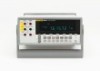
1 Introduction and Specifications Introduction Introduction The Fluke 8808A Digital Multimeter (hereafter referred to as the Meter) is a 5-1/2 digit dual-display multimeter designed for bench-top, field service, and system applications. The multiple measurement functions, plus the RS-232 remote - Fluke 8808A | User Manual - Page 14
8808A Users Manual About this Manual This manual contains all the information a new user will need to operate the Meter effectively. This manual is divided into the following chapters: Chapter 1, "Introduction and Specifications," provides information on how safely to use install, use or service the - Fluke 8808A | User Manual - Page 15
Specifications Safety Information Table 1-1. Safety Information XW Warning To avoid possible electric shock, personal injury, or death, read the following before using the Meter: • Use the Meter only as specified in this manual, or the protection provided by the Meter might be impaired. • Do not use - Fluke 8808A | User Manual - Page 16
Y U < ~ CAT I Description Standby power ON / OFF Earth ground Capacitance Diode Fuse Digital signal Maintenance or Service Recycle Do not dispose of this product as unsorted municipal waste. Contact Fluke or a qualified recycler for disposal. Measurement Category I is for measurements not directly - Fluke 8808A | User Manual - Page 17
RS-232 Cable (2 m) Precision Electronic Prob Set 2X4 Wire Ohms 1000 V Test Lead FlukeView Forms Basic Software FlukeView Forms Software Upgrade to enhanced version 1 Introduction and Specifications Options and Accessories Model / Part Number TL71 163030 166488 803293 943121 Y8846S Y8846D RS43 TL910 - Fluke 8808A | User Manual - Page 18
8808A Users Manual General Specifications Voltage 100V Setting 90 V to 110 V 120V Setting 108 V to 132 V 220V Setting 198 V to 242 V 240V 50 °C Storage 40 °C to 70 °C Warm Up hour to full uncertainty specifications Relative Humidity (non-condensing) Operating Uncontrolled (< 10°C) - Fluke 8808A | User Manual - Page 19
all functions except continuity and diode test Remote Interfaces RS-232C Warranty One year Electrical Specifications Accuracy specifications are valid for 5-½ digit mode and after at least a half-hour warm-up DC Voltage Specifications Maximum Input 1000 V on any range Common Mode Rejection 120 - Fluke 8808A | User Manual - Page 20
8808A Users Manual AC Voltage Specifications AC Voltage specifications are for ac sinewave signals >5 % of range. of full scale Crest Factor 2-3, 0.2 % of full scale Input Characteristics Range Full-Scale (5-1/2 Digits) Slow Resolution Medium Fast Input Impedance 200 mV 2 V 20 V 200 V 750 V - Fluke 8808A | User Manual - Page 21
Specifications Electrical Specifications Resistance Specifications are for 4-wire resistance function, or 2-wire resistance with REL. If REL is not used 200 uA and 2 mA range. Input Characteristics Range Full-Scale (5-1/2 Digits) Slow Resolution Medium Fast Burden Voltage 200 uA 2 mA 20 mA - Fluke 8808A | User Manual - Page 22
8808A Users Manual Accuracy Accuracy [1] Range 90 0.001 0.008 + 0.001 AC Current The following ac current specifications are for sinusoidal signals with amplitudes greater than 5 % of range of full scale Range Full-Scale (5-1/2 Digits) Input Characteristics Resolution Slow Medium Fast - Fluke 8808A | User Manual - Page 23
1 Introduction and Specifications Electrical Specifications Frequency Gate Time 131 ms Measurement Method AC-coupled input using the ac voltage measurement function. Settling Considerations When measuring frequency after a dc offset voltage change, errors may occur. For the most accurate - Fluke 8808A | User Manual - Page 24
8808A Users Manual 1-14 - Fluke 8808A | User Manual - Page 25
Chapter 2 Preparing the Meter for Operation Title Page Introduction...2-3 Unpacking and Inspecting the Meter 2-3 Contacting Fluke 2-3 Storing and Shipping the Meter 2-3 Power Considerations 2-3 Selecting the Line Voltage 2-4 Replacing the Fuses 2-4 Line-Power Fuse 2-4 Current-Input Fuses - Fluke 8808A | User Manual - Page 26
8808A Users Manual 2-2 - Fluke 8808A | User Manual - Page 27
To order accessories, receive operating assistance, or get the location of the nearest Fluke distributor or Service Center, call: USA: Canada: Europe: Japan: Singapore: Anywhere in the world: 1-888-99-FLUKE (1-888-993-5853) 1-800-36-FLUKE (1-800-363-5853) +31 402-675-200 +81-3-3434-0181 +65-738 - Fluke 8808A | User Manual - Page 28
8808A Users Manual Selecting the Line Voltage The Meter operates on four Replace the selector block back into the fuse holder. XW Warning To avoid electric shock or fire, do not use makeshift fuses or short-circuit the fuse holder. Table 2-1. Line Voltage to Fuse Rating Line Voltage Selection 100 - Fluke 8808A | User Manual - Page 29
eue20.eps Current-Input Fuses The 200 mA and 10 A inputs are protected by user-replaceable fuses. • The 200 mA input is protected by a fuse (F2) set the range to 200 Ω. Only the 200 Ω, 2 kΩ, and 20 kΩ ranges can be used to test the mA input fuse. 4. Insert the other end of the test lead into the mA - Fluke 8808A | User Manual - Page 30
8808A Users Manual 1. Remove power from the Meter by unplugging its power cord. 2. Turn the Meter upside down. 3. Remove the retaining screw on the fuse access door located - Fluke 8808A | User Manual - Page 31
line power cord to a properly grounded power outlet. Do not use a two-conductor adapter or extension cord, as this will break the grounded three-prong outlet. See Figure 23 for line-power cord types available from Fluke. Refer to Table 2-2 for descriptions of the line-power cords. LC-1 LC - Fluke 8808A | User Manual - Page 32
8808A Users Manual Turning Power On 1. If required, connect the Meter to line power. 2. Toggle the power the Meter into an Equipment Rack The Meter is mountable in a standard 19-inch rack using a rack mount kit. See the "Options and Accessories" section in Chapter 1 for ordering information. 2-8 - Fluke 8808A | User Manual - Page 33
25. To install the Meter into the rack, refer to the instructions provided with the Rack Mount Kit. Figure 2-5. Boot Removal eue22.eps use aromatic hydrocarbons, alchohol, chlorinated solvents, or methanol-based fluids when wiping down the Meter. Fluke 45 Emulation To switch the Meter to Fluke - Fluke 8808A | User Manual - Page 34
8808A Users Manual Press Uor Vto scroll between F8808A and F45. The presently selected mode will appear bright in the display, while the other is dim. Press R to - Fluke 8808A | User Manual - Page 35
Modifier (REL 3-18 Decibels and Auto Power Modifier 3-18 Touch Hold Function (HOLD 3-19 Minimum / Maximum Modifier (MIN MAX 3-20 Using the Function Modifiers in Combination 3-21 Second Level Operations (Using the SHIFT Button 3-21 Compare Function (COMP 3-22 Setting the Compare Range 3-22 - Fluke 8808A | User Manual - Page 36
8808A Users Manual Calibration ...3-25 3-2 - Fluke 8808A | User Manual - Page 37
measurement and display a reading • Select the manual or autorange mode • Manually select a measurement range for the primary display slow, medium, fast) • Take a measurement and compare it against a tolerance range • Use the editor to select from option lists, to enter a relative base, or to enter - Fluke 8808A | User Manual - Page 38
8808A Users Manual 1 2 3 4 2W/4W HI INPUT V SENSE 4W HI 1000V 750V MAX LO 200 mA MAX 1000 V 600 V CAT I CAT II 300 V 1V LO 500 Vpk 10 A MAX mA 10 A 8808A 5-1/2 DIGIT MULTIMETER 4-Wire Ohms, and Hz measurements. All measurements use the INPUT LO terminal as a common input Calibrates - Fluke 8808A | User Manual - Page 39
: Frequency DC voltage AC voltage DC current AC current Resistance (ohms) Continuity / diode test (toggles) Toggles between manual and autorange modes Uand V increase and decrease the range for manual ranging Input terminal for 10 A ac and dc current measurement Input terminal for 200 mA ac and dc - Fluke 8808A | User Manual - Page 40
8808A Users Manual Dual Display The Meter has a 5-1/2 digit vacuum fluorescent dual display. See Figure 3-2 and Table of the dual display, and consists of the larger digits and annunciators. The primary display shows measurements taken using the relative readings (REL), minimum maximum (MIN MAX), - Fluke 8808A | User Manual - Page 41
Slow, Medium, Fast Q - R Setup 8 annunciator S Print T * (asterisk) U Auto Range V Manual Range W CAL Error X Y Description Meter is in remote mode (remotely controlled) the front panel is locked out mode Meter is in manual range mode Calibration attempt failed High voltage is detected Displays when voltage is >30 - Fluke 8808A | User Manual - Page 42
8808A Users Manual Rear Panel See Figure 3-3 and Table 3-3 for an overview of the rear-panel features. 1 2 to ground Adjusting Meter Range Ranging operations are performed using R, Uand V. Press R to toggle between autorange and manual range modes. When autoranging is selected, Auto Range - Fluke 8808A | User Manual - Page 43
range. The Meter remains in the selected range regardless of input. Manual ranging can only be performed on readings shown on the primary display. display uses the same range as the primary display. Selecting a Measurement Rate The Meter takes measurements at one of three user-selected rates - Fluke 8808A | User Manual - Page 44
8808A Users Manual Measuring Voltage The Meter is capable of measuring voltage up to 1000 V dc and 750 V ac. W Caution To avoid possible damage to the Meter, do - Fluke 8808A | User Manual - Page 45
primary display only. If you manually select a frequency range and the measurement exceeds the full-scale value of that range, 0L is displayed to indicate an overload. If the frequency is lower than 20 Hz, UL is displayed. Refer to the "Electrical Specifications" section in Chapter 1 for frequency - Fluke 8808A | User Manual - Page 46
8808A Users Manual 4-Wire Resistance Measurement The Meter incorporates two methods of making a four-wire resistance measurement. The traditional method is to use Resistance Measurement eue12.eps To make a four-wire resistance measurement using Fluke's 2X4 test leads: 1. Connect the test leads to - Fluke 8808A | User Manual - Page 47
Vpk 10 A MAX mA 10 A Figure 3-7. Input Connections for 4-Wire Ohms Using 2x4 Wire Leads eue26.eps Measuring Current W Caution To avoid blowing the current circuit under test. 3. If the circuit current is unknown, start by using the 10 A and LO terminals. 4. If the measurement is expected to - Fluke 8808A | User Manual - Page 48
8808A Users Manual I < 200 mA V AC 2W/4W HI INPUT V SENSE 4W HI 1000V 750V MAX LO 200 mA MAX 1000 V 600 V CAT I CAT II 300 V 1V LO - Fluke 8808A | User Manual - Page 49
3 Operating the Meter from the Front Panel Selecting a Measurement Function Diode / Continuity Testing Press G to toggle between the continuity and diode test functions for the primary display. (These functions cannot be selected for the secondary display.) To perform a continuity test: 1. If - Fluke 8808A | User Manual - Page 50
8808A Users Manual 2W/4W HI INPUT V SENSE 4W HI 1000V 750V MAX LO 200 mA MAX the "Electrical Specifications" section in Chapter 1 for information on this signal. The following sections discuss triggering the Meter automatically using its internal trigger, or externally using the trigger key - Fluke 8808A | User Manual - Page 51
Description +5 V OUT RS-232 TXD Trigger Out Pin # 2 5 9 Description RS-232 RXD RS-232 GND Trigger In eue23.eps Figure 3-12 shows a method for using the +5V OUT (pin 1) signal with an external switch to trigger the Meter. +5 V Out (Pin 1) Trig In (Pin 9) Figure 3-12. External Trigger Circuit - Fluke 8808A | User Manual - Page 52
8808A Users Manual After a function modifier is selected, pressing any function button turns display. (The secondary display is unaffected.) To edit the relative base, use the number editor as described in the "Using the Number Editor" section later in this chapter. Selecting the relative readings - Fluke 8808A | User Manual - Page 53
Setting the dB reference resistance to 16, 8, 4, or 2 ohms allows you to use the Meter to calculate audio power. After the reference resistance has been set to 16 , you will autorange to the correct range. If you are in the manual range mode when Touch Hold is selected, you will be in the fixed - Fluke 8808A | User Manual - Page 54
8808A Users Manual • Level 1 (0.01 % of reading) • Level 2 (0.1 % of reading) • Level 3 (1 % of reading) • Level 4 (10 % of reading) To change the response level, press Q and I. The response level currently - Fluke 8808A | User Manual - Page 55
) Edits compare mode low point (see the "Using the Compare Function" section later in this manual) Edits compare mode high point (see the "Using the Compare Function" section later in this manual) In relative mode, toggles display of relative base in secondary display Displays software version 3-21 - Fluke 8808A | User Manual - Page 56
8808A Users Manual Table 3-6. Second Level Operations (cont.) Buttons Q and V[1] Q and U[1] Description In COMP mode, stores value on primary display as LO compare point (see the "Using the Compare Function" section later in this manual) In COMP mode, stores value on primary display as HI compare - Fluke 8808A | User Manual - Page 57
select the options described in Table 3-7. You may abort an edit and return to normal operation at any time by pressing Q. To use the list editor: 1. Select the option list that you want to edit by pressing the applicable button(s) as indicated in Table 3-7. The option list type - Fluke 8808A | User Manual - Page 58
8808A Users Manual Using the Number Editor Use the number editor to edit the relative base through S6 to select the next digit to edit. S1 corresponds to the left-most digit and S6 corresponds to the right-most digit. Repeat this step until you have set all the digits to their desired values. 3. - Fluke 8808A | User Manual - Page 59
and on. These parameters remain as set until changed by the user. Table 3-9. Factory Power-Up Configuration Parameter Configuration Function setting DC Trigger type 1 (Internal) Trigger trype 0 Calibration Refer to the 8808A Calibration Manual for instructions on calibrating the Meter. 3-25 - Fluke 8808A | User Manual - Page 60
8808A Users Manual 3-26 - Fluke 8808A | User Manual - Page 61
-232 4-3 RS-232 Print-Only Mode 4-4 Cabling the Meter to a Host or Printer (RS-232 4-5 Character Echoing and Deletion 4-6 Device Clear Using ^C (CNTRL C 4-6 RS-232 Prompts 4-6 Getting Started with an Installation Test 4-6 Installation Test for RS-232 Operation 4-6 If Test Fails...4-7 How the - Fluke 8808A | User Manual - Page 62
8808A Users Manual Compare Commands and Queries 4-24 Trigger Configuration Commands 4-24 Miscellaneous Commands and Queries 4-25 RS-232 Remote / Local Configurations 4-25 RS-232 Save / Recall System Configurations 4-26 Sample Program Using the RS-232 Computer Interface 4-27 4-2 - Fluke 8808A | User Manual - Page 63
be operated from a host (a terminal, controller, PC, or computer) by sending commands to the Meter through its computer interface. An annotated sample program illustrating the use of the RS-232 computer interface is provided at the end of this chapter. Refer to Chapter 3 for complete descriptions of - Fluke 8808A | User Manual - Page 64
8808A Users Manual 6. Press R to review the settings. When you are ready to accept the The print-only mode is used to send measurements to a printer or terminal automatically. While the Meter will respond to remote commands during print-only operations, Fluke recommends first setting the Meter's - Fluke 8808A | User Manual - Page 65
than 2500 pf. To connect the Meter to a personal computer (with DB-9 connector), use a Fluke RS41-3 Null modem cable. Refer to Table 1-3. To connect the Meter to a specific brand of RS-232 printer, use the cable that would be used to connect that printer to an RS-232 port on a personal computer with - Fluke 8808A | User Manual - Page 66
8808A Users Manual was understood, but not executed. For example, user attempted to use FREQ to perform a VDC measurement. Getting Started with sends the following response: FLUKE, 8808A, nnnnnnn, n.n Dn.n Where nnnnnnn is the Meter's serial number; n.n is the main software version; and Dn.n is - Fluke 8808A | User Manual - Page 67
) is detected, a device-dependent error is generated and the input string is discarded. If the Meter's input buffer becomes full when it is used with the RS-232 interface, a device-dependent error is generated (see "Event Status and Event Status Enable Register") and the input string is discarded - Fluke 8808A | User Manual - Page 68
8808A Users Manual In some instances, a terminator is automatically transmitted at the end of the instrument (if any) 4. The terminator Note If MEAS?, MEAS1? or MEAS2? is used, the command should follow Configure, Trigger. How the Meter Processes Output The following paragraphs describe how - Fluke 8808A | User Manual - Page 69
External trigger, which triggers a measurement at the direction of the user. A measurement can be externally triggered as follows: • External trigger includes trigger types 4 and 5, as described in Table 4-3. • *TRG command For use of the *TRG command, see "Common Commands." Type 1 2 3 4 5 - Fluke 8808A | User Manual - Page 70
8808A Users Manual If you enter the remote mode with trigger type 4 or 5 selected, 5), *TRG command is always available. Setting the Trigger Type Configuration To set the trigger type configuration using the computer interface, enter the command TRIGGER (where is the trigger type) and - Fluke 8808A | User Manual - Page 71
4 Operating the Meter Using the Computer Interface Status Registers Status Registers The contents of the status register (STB) are determined by the service enable register (SRE), event status register (ESR), event status enable register (ESE), and the output buffer. These status registers are - Fluke 8808A | User Manual - Page 72
8808A Users Manual UQCDEOPRsuxoepoeeeveeirmwrqrccyeuaumrRteteiiaEesorontODqrnndneuoCrpeCEEoersrotrnrntoormdrropellnetteError Logical OR 7 65432 10 Standard Event Status Register & & &&& & && Read Using *ESR? Standard Queue Not-Empty 7 6 5 4 3 2 1 0 Event Status Enable Register Read - Fluke 8808A | User Manual - Page 73
to 1, the ESB bit in the STB also changes to 1. When the ESR is read using the *ESR? command or cleared using the *CLS command, the ESB bit in the STB returns to 0. Power On User Request Command Error Execution Error Device Dependent Error Query Error Request Control Operation Complete Logical OR - Fluke 8808A | User Manual - Page 74
8808A Users Manual 4-14 Table 4-6. Description of Bits in ESR and ESE Bit No. Name Condition 0 Operation Complete (OPC) All commands before receipt of an *OPC command have been executed. Interface is ready to accept another message. 1 Not used Incorrect input during calibration. Or RS- - Fluke 8808A | User Manual - Page 75
) is set to 1 if service requested from front panel or MSS is set to 1. Status of bit is returned by serial poll, which clears RQS. 7 Not used Always set to 0. [1] As read by * Parameters that must be supplied by the user or strings returned by the Meter are enclosed in angle brackets (for example, - Fluke 8808A | User Manual - Page 76
8808A Users Manual Common Commands Table 4-8 describes common commands. Command *CLS *ESE *ESE? *ESR? by commas. These fields are: Manufacturer (FLUKE); model (8808A); seven-digit serial number; and versions of main software and display software. Operation Complete Command Meter sets the - Fluke 8808A | User Manual - Page 77
Request Enable Register to , where is an integer between 0 and 255. The value of bit 6 is ignored because the Service Request Enable Register does not use it. is an integer whose binary equivalent corresponds to the state (1 or 0) of bits in the register. If is not - Fluke 8808A | User Manual - Page 78
8808A Users Manual Table 4-9. Function Commands and Queries (cont.) Commands Primary Display Secondary example, if frequency is selected, FUNC2? returns FREQ If secondary display is not in use, an Execution Error is generated. OHMS OHMS2 Resistance WIRE2, WIRE4 (Not applicable) Only - Fluke 8808A | User Manual - Page 79
4 Operating the Meter Using the Computer Interface Computer Interface Command Set Function Modifier Commands and Queries Table 4-10 describes function modifier commands and queries. A function modifier causes the Meter - Fluke 8808A | User Manual - Page 80
8808A Users Manual Table 4-10. Function Modifier Commands and Queries (cont.) Command Description HOLDTHRESH? Meter returns Touch Hold (1, 2, 3, or 4). See "Touch Hold Function (HOLD)" in Chapter 3 for - Fluke 8808A | User Manual - Page 81
are selected, 40 is returned. Meter enters the relative readings modifier (REL) using the value shown on the primary display as the relative base. Autoranging is disabled automatically selects a range for each reading. In manual range mode, the user selects a fixed range. Table 4-11. Range and - Fluke 8808A | User Manual - Page 82
8808A Users Manual Table 4-11. Range and Measurement Rate Commands and Queries (cont.) Command RANGE Description Sets the primary display to where - Fluke 8808A | User Manual - Page 83
of Format 2: +1.2345E+0 VDC, +6.7890E+3 ADC If the secondary display is not on, MEAS? is equivalent to MEAS1? Note: If MEAS is used in external trigger (TRIGGER 2 through TRIGGER 5), unexpected results will be obtained. Meter returns the value shown on the primary display. If the primary - Fluke 8808A | User Manual - Page 84
8808A Users Manual Compare Commands and Queries Table 4-13 describes the compare commands and queries. These commands cause the Meter to determine whether a measurement is higher than, lower - Fluke 8808A | User Manual - Page 85
VAC ADC AAC OHMS HZ VDC OHMS RS-232 Remote / Local Configurations Table 4-17 describes the RS-232 remote and local configuration commands, which are used with the RS-232 interface to set up the remote/local configuration of the Meter. These commands are valid only when the RS-232 interface - Fluke 8808A | User Manual - Page 86
8808A Users Manual Command REMS RWLS LOCS LWLS Table 4-17. Remote/Local Save / Recall System Configurations Table 4-18 describes RS-232 save/recall system configuration commands, which are used with the RS-232 interface to set up the remote/local configuration of the Meter. Command Save - Fluke 8808A | User Manual - Page 87
4 Operating the Meter Using the Computer Interface Sample Program Using the RS-232 Computer Interface Sample Program Using the RS-232 Computer Interface Figure 4-4 is an annotated BASIC A program written for a PC that demonstrates how the Meter can be used with the RS-232 computer interface. Figure - Fluke 8808A | User Manual - Page 88
8808A Users Manual 4-28 - Fluke 8808A | User Manual - Page 89
Appendices Appendix Title Page A Applications ...A-1 B 2X4 Test Leads B-1 - Fluke 8808A | User Manual - Page 90
8808A Users Manual - Fluke 8808A | User Manual - Page 91
basic operation of the Meter and have a basic understanding of electronics. A sophisticated understanding of electrical circuits is not necessary. Using the Dual Display Using the dual display effectively and with ingenuity can greatly enhance your test and measurement capabilities. The dual display - Fluke 8808A | User Manual - Page 92
8808A Users Manual Figure A-1. Example of Dual Display Showing Volts AC and Frequency eue25.eps Using Measurement Functions the secondary display. Additional combinations of dual readings can be added by using the relative readings, minimum/maximum, and/or Touch Hold function modifiers. - Fluke 8808A | User Manual - Page 93
Value Applications • Monitor dc level and ac ripple of power supply Troubleshoot amplifier circuits • Check power supply load regulation • Monitor UUT of switching power supply • Measure current dissipation in protective fuse resistors used in power supplies • Measure ripple and noise on a line • - Fluke 8808A | User Manual - Page 94
8808A Users Manual Primary Display REL HOLD Table A-2. Sample Dual Display Applications (cont.) Secondary Display Resistance Actual Value Applications • Select and sort resistors. (See also "Using 500 Vpk 10 A MAX mA 10 A 8808A 5-1/2 DIGIT MULTIMETER Figure A-2. DC Voltage and DC Current - Fluke 8808A | User Manual - Page 95
is used, or two measurements when both the primary and secondary display are used), the input level, range type (autorange or manual range), settled in order for the displayed result to meet the meter's accuracy specifications. This "settling delay" varies, depending on the differences between the - Fluke 8808A | User Manual - Page 96
8808A Users Manual Table A-3. Typical Single Measurement Response Times (in Seconds) Slow Rate Medium Rate Fast Rate Meas. Function Auto Range[1] Single Range[2] Auto Range[1] Single Range[2] Auto - Fluke 8808A | User Manual - Page 97
N/A N/A Fast 0.9 0.8 0.9 0.8 N/A N/A N/A External Trigger The external trigger can be used with or without settling delays, as shown in Table A-4. (Refer to Table 4-3 for trigger additional source of error. Thermal voltages can also cause problems in the low ohms ranges. Some low-value resistors - Fluke 8808A | User Manual - Page 98
8808A Users Manual Making Low-Level Current Measurements There are many applications mode is critical in determining the time before battery recharge is needed. Traditional multimeters make these measurements using a shunt method shown in Figure A-3. The shunt resistor converts the current to - Fluke 8808A | User Manual - Page 99
Appendix B 2X4 Test Leads Introduction The optional Fluke TL2X4W test leads simplify making 4-wire ohms electric shock and possible damage to the Meter, use the 2X4 Wire test leads as specified in this manual. Inspect the test leads before use. Do not use them if insulation is damaged or metal is - Fluke 8808A | User Manual - Page 100
8808A Users Manual B-2
-
 1
1 -
 2
2 -
 3
3 -
 4
4 -
 5
5 -
 6
6 -
 7
7 -
8
-
9
-
10
-
11
-
12
-
13
-
14
-
15
-
16
-
17
-
18
-
19
-
20
-
21
-
22
-
23
-
24
-
25
-
26
-
27
-
28
-
29
-
30
-
31
-
32
-
33
-
34
-
35
-
36
-
37
-
38
-
39
-
40
-
41
-
42
-
43
-
44
-
45
-
46
-
47
-
48
-
49
-
50
-
51
-
52
-
53
-
54
-
55
-
56
-
57
-
58
-
59
-
60
-
61
-
62
-
63
-
64
-
65
-
66
-
67
-
68
-
69
-
70
-
71
-
72
-
73
-
74
-
75
-
76
-
77
-
78
-
79
-
80
-
81
-
82
-
83
-
84
-
85
-
86
-
87
-
88
-
89
-
90
-
91
-
92
-
93
-
94
-
95
-
96
-
97
-
98
-
99
-
100
 |
 |

®
8808A
Digital Multimeter
Users Manual
July 2007
© 2007 Fluke Corporation, All rights reserved.
All product names are trademarks of their respective companies.