Foxconn FlamingBlade GTI English Manual. - Page 25
Audio Connector : F_AUDIO, Fan Connectors : CPU_FAN1, SYS_FAN1, NB_FAN1, VFD Connector : VFD
 |
View all Foxconn FlamingBlade GTI manuals
Add to My Manuals
Save this manual to your list of manuals |
Page 25 highlights
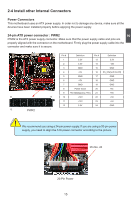
2 Audio Connector : F_AUDIO The audio connector supports HD Audio standard. It provides the Front Audio output choice. Fan Connectors : CPU_FAN1, SYS_FAN1, NB_FAN1 There are three fan headers on this motherboard. These fans can be automatically turned off after the system enters S3, S4 and S5 sleeping states. PORT1_L PORT1_R PORT2_R SENSE_SEND PORT2_L 12 9 10 AUD_GND PRESENCEJ SENSE1_RETURN EMPTY SENSE2_RETURN F_AUDIO 1 GND +12V SENSE SYS_FAN1/ NB_FAN1 1 GND POWER SENSE CONTROL CPU_FAN1 VFD Connector : VFD The VFD Connector can be connected to the Foxconn Quantum Force OC Panel, which can be installed in any standard 5.25" optical drive bay. It can be used to display the Port80 Debug codes during Bootup, display the system Real Time Clock, display the system temperatures as well as monitor and adjust System voltages and clockspeeds on the fly. With several buttons located on the front panel, you can easily set the Front Side Bus speed, adjust CPU, DRAM and VTT NB voltage and change the fan speeds. It supports profiles which can be loaded within fractions of a second by pushing a single button. You can purchase it to overclock your system on the fly, switch from one oc profile to another during a benchmark, switch from gaming mode to cinema or silent mode. RESET 5V 12 ISP GPIO EMPTY GPIO 3.3V NC GND GPIO SDA SCL RXD TXD 13 14 VFD 18
-
 1
1 -
2
-
3
-
4
-
5
-
6
-
7
-
8
-
9
-
10
-
11
-
12
-
13
-
14
-
15
-
16
-
17
-
18
-
19
-
 20
20 -
 21
21 -
 22
22 -
 23
23 -
 24
24 -
 25
25 -
 26
26 -
 27
27 -
 28
28 -
 29
29 -
 30
30 -
31
-
32
-
33
-
34
-
35
-
36
-
37
-
38
-
39
-
40
-
41
-
42
-
43
-
44
-
45
-
46
-
47
-
48
-
49
-
50
-
51
-
52
-
53
-
54
-
55
-
56
-
57
-
58
-
59
-
60
-
61
-
62
-
63
-
64
-
65
-
66
-
67
-
68
-
69
-
70
-
71
-
72
-
73
-
74
-
75
-
76
-
77
-
78
-
79
-
80
-
81
-
82
-
83
-
84
-
85
-
86
-
87
-
88
-
89
-
90
-
91
-
92
-
93
-
94
-
95
-
96
-
97
-
98
-
99
-
100
-
101
-
102
-
103
-
104
-
105
-
106
-
107
-
108
-
109
-
110
-
111
-
112
-
113
-
114
-
115
-
116
-
117
-
118
-
119
-
120
-
121
-
122
 |
 |
