Foxconn Q67M-S English Manual - Page 21
Install other Internal Connectors
 |
View all Foxconn Q67M-S manuals
Add to My Manuals
Save this manual to your list of manuals |
Page 21 highlights
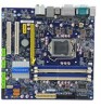
2 CAUTION 2-4 Install other Internal Connectors Power Connectors This motherboard uses an ATX power supply. In order not to damage any device, make sure all the devices have been installed properly before applying the power supply. 24-pin ATX Power Connector : PWR1 PWR1 is the ATX power supply connector. Make sure that the power supply cable and pins are properly aligned with the connector on the motherboard. Firmly plug the power supply cable into the connector and make sure it is secure. Pin # Definition Pin # Definition 1 3.3V 13 3.3V 2 3.3V 14 -12V 3 GND 15 GND 4 +5V 16 PS_ON(Soft On/Off) 5 GND 17 GND 6 +5V 18 GND 7 GND 19 GND 8 Power Good 20 NC 9 +5V SB(Stand by +5V) 21 +5V 24 13 10 +12V 22 +5V 11 +12V 23 +5V 12 3.3V 24 GND 12 PWR1 1 ! We recommend you using a 24-pin power supply. If you are using a 20-pin power supply, you need to align the ATX power connector according to the picture. Pin No. 24 20-Pin Power 4-pin ATX 12 V Power Connector : PWR2 Connect the 8-pin ATX 12V power supply to PWR2 and provides power to the CPU. +12V 3 1 4 2 PWR2 GND Pin # 1 2 3 4 Definition GND GND +12V +12V 14
-
 1
1 -
2
-
3
-
4
-
5
-
6
-
7
-
8
-
9
-
10
-
11
-
12
-
13
-
14
-
15
-
 16
16 -
 17
17 -
 18
18 -
 19
19 -
 20
20 -
 21
21 -
 22
22 -
 23
23 -
 24
24 -
 25
25 -
 26
26 -
27
-
28
-
29
-
30
-
31
-
32
-
33
-
34
-
35
-
36
-
37
-
38
-
39
-
40
-
41
-
42
-
43
-
44
-
45
-
46
-
47
-
48
-
49
-
50
-
51
-
52
-
53
-
54
-
55
-
56
-
57
-
58
-
59
-
60
-
61
-
62
-
63
-
64
-
65
-
66
-
67
-
68
-
69
-
70
-
71
-
72
-
73
-
74
-
75
-
76
-
77
-
78
-
79
-
80
-
81
-
82
-
83
-
84
-
85
-
86
-
87
-
88
-
89
-
90
-
91
-
92
-
93
-
94
-
95
-
96
-
97
-
98
-
99
-
100
-
101
-
102
-
103
-
104
-
105
-
106
-
107
-
108
-
109
-
110
 |
 |
