Foxconn Rattler User manual - Page 27
OnBoard Debug LED - oc
 |
View all Foxconn Rattler manuals
Add to My Manuals
Save this manual to your list of manuals |
Page 27 highlights
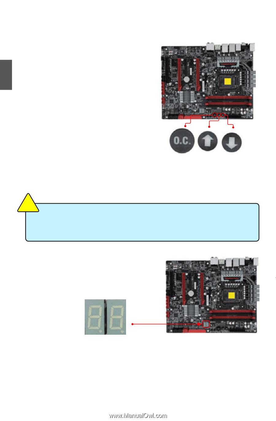
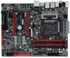
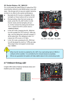
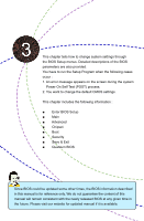
2 CAUTION OC Switch Button: OC_SW1/2/3 You could press the three buttons to adjust the CPU clock directly, without to enter BIOS setup or any software. This process will not use any system resource, so there is no effect to the system performance. ■ Normally the OC function is disabled. All the led lights on these buttons will be turned off. ■ During booting, when the boot screen appears, press the OC_SW1 button to enter the OC mode and the led lights will turn on. At this moment the debug led will show "0.0". It means the CPU current clock is 100MHz(Default). ■ In the OC mode, pressing the OC_SW2 button will increase the CPU clock by 1 MHz per step, and the debug led code will increase 0.1 at the same time. The debug led code "0.1" means the CPU clock is 101 MHz. ■ In the OC mode, pressing the OC_SW3 button will decrease the clock by 1 MHz per step. This project does not support a clock lower than 100MHz. OC_SW1 OC_SW2 OC_SW3 ! ■ When the OC function is enabled by OC_SW1, the overclocking items in BIOS or software will be availble. It is controlled by the onboard buttons completely. ■ We do not guarantee the system will keep stable status In the overclocking mode. 2-7 OnBoard Debug LED 2-digital LED readout displays hardware status and enables quick error diagnosis. 20 20
-
 1
1 -
2
-
3
-
4
-
5
-
6
-
7
-
8
-
9
-
10
-
11
-
12
-
13
-
14
-
15
-
16
-
17
-
18
-
19
-
20
-
21
-
 22
22 -
 23
23 -
 24
24 -
 25
25 -
 26
26 -
 27
27 -
 28
28 -
 29
29 -
 30
30 -
 31
31 -
 32
32 -
33
-
34
-
35
-
36
-
37
-
38
-
39
-
40
-
41
-
42
-
43
-
44
-
45
-
46
-
47
-
48
-
49
-
50
-
51
-
52
-
53
-
54
-
55
-
56
-
57
-
58
-
59
-
60
-
61
-
62
-
63
-
64
-
65
-
66
-
67
-
68
-
69
-
70
-
71
-
72
-
73
-
74
-
75
-
76
-
77
-
78
-
79
-
80
-
81
-
82
-
83
-
84
-
85
-
86
-
87
-
88
-
89
-
90
-
91
-
92
-
93
-
94
-
95
-
96
-
97
-
98
-
99
-
100
-
101
-
102
-
103
-
104
-
105
-
106
-
107
-
108
-
109
-
110
-
111
 |
 |