Frigidaire CGEF302TPF Wiring Diagram - Page 1
Frigidaire CGEF302TPF Manual
 |
View all Frigidaire CGEF302TPF manuals
Add to My Manuals
Save this manual to your list of manuals |
Page 1 highlights
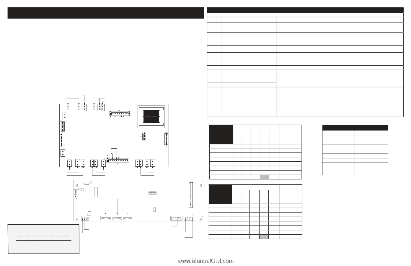
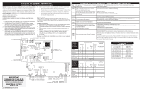
SERVICE DATA SHEET Electric Ranges with ES610 Electronic Oven Controls NOTICE: This service data sheet is intended for use by persons having electrical and mechanical training and a level of knowledge of these subjects generally considered acceptable in the appliance repair trade. The manufacturer cannot be responsible, nor assume any liability, for injury or damage of any kind arising from the use of this data sheet. IMPORTANT NOTE: This unit includes an EOC (electronic oven control). This board is not field-repairable. • All electrical leads are properly dressed and secured away from sharp edges, high-temperature components, and moving parts. • All uninsulated electrical terminals, connectors, heaters, etc. are adequately spaced away from all metal parts and panels. • All safety grounds (both internal and external) are correctly and securely reassembled. • All panels are properly and securely reassembled. Safe Servicing Practices To avoid the possibility of personal injury and/or property damage, it is important that safe servicing practices be observed. The following are some, but not all, examples of safe practices. Oven Calibration Set the electronic oven control for normal baking at 350°F. Allow oven to preheat to set temperature. Obtain an average oven temperature after a minimum of five cycles. Press the STOP key to end the Bake mode. 1. Do not attempt a product repair if you have any doubts as to your ability to complete it in a safe and satisfactory manner. 2. Before servicing or moving an appliance, remove power cord from electric outlet, trip circuit breaker to Off, or remove fuse. 3. Never interfere with the proper installation of any safety device. 4. Use only replacement parts specified for this appliance. Substitutions may not comply with safety standards set for home appliances. 5. Grounding: The standard color coding for safety ground wires is green or green with yellow stripes. Ground leads are not to be used as current carrying conductors. It is extremely important that the service technician reestablish all safety grounds prior to completion of service. Failure to do so will create a potential hazard. 6. Prior to returning the product to service, ensure that: • All electric connections are correct and secure. Temperature Adjustment 1. While in a non-cooking mode, press and hold the Bake key for 6 seconds. 2. The current calibration offset (temperature adjustment) should appear in the tempera- ture display. 3. Use the number keys (0-9) to enter the desired amount of adjustments (up to 35°F). 4. Press the Self Clean key to change the sign of the adjustment to a (-), if necessary. A positive adjustment will not display a sign. 5. Once the desired adjustment (-35° to 35° F) has been entered, press the Start key to accept the change or the Cancel key to reject the change. Note: Changing calibration affects all baking modes. The adjustments made will not change the self-cleaning temperature. P12 P2 L2 OUT LOWER OVEN P10 BAKE LOWER OVEN P18 P8 BROIL LOWER OVEN P4 L2 IN LOWER OVEN TO USER INTERFACE BOARD J6 TO CONTROL BOARD J4 (GRAY) J2 TO CONTROL BOARD P2 (GREEN) P6 L1 LOWER OVEN NEUTRAL J7 TO CONTROL L1 LOWER OVEN BOARD J5 (PURPLE) MDL LOWER OVEN OVEN LAMP LOWER OVEN J5 TO CONTROL BOARD J3 (WHITE) OVEN LAMP UPPER OVEN MDL UPPER OVEN P5 L1 UPPER OVEN L1 UPPER OVEN NEUTRAL P7 BROIL UPPER OVEN P9 BAKE UPPER OVEN P11 IMPORTANT DO NOT REMOVE THIS BAG OR DESTROY THE CONTENTS WIRING DIAGRAMS AND SERVICE INFORMATION ENCLOSED REPLACE CONTENTS IN BAG p/n 807949901 Rev A (14/11) P1 L2 OUT UPPER OVEN P17 P3 L2 IN UPPER OVEN P2 TO RELAY BOARD J2 (GREEN) P6 TO RELAY BOARD J6 (GRAY) TO RELAY BOARD J5 (WHITE) TO RELAY BOARD J7 (PURPLE) J3 J4 J5 P6 P15 LX IN P19 P13 WARM ZONE J2 P1 P10 P8 UPPER OVEN TEMP PROBE UPPER OVEN TEMP PROBE LOWER OVEN TEMP PROBE LOWER OVEN TEMP PROBE LOWER OVEN COMMON LOWER OVEN DOOR SWITCH LOWER OVEN LOCK SWITCH UPPER OVEN COMMON UPPER OVEN DOOR SWITCH UPPER OVEN LOCK SWITCH ELECTRONIC OVEN CONTROL (EOC) FAULT CODE DESCRIPTIONS Note: Generally speaking "F1x" implies a control failure, "F3x" an oven probe problem, and "F9x" a latch motor problem. Code Condition / Cause Suggested Corrective Action Control has sensed a potential runaway oven - Check RTD sensor probe and replace if necessary. If oven is overheating, disconnect power. If oven continues to F10 condition. Control may have shorted relay, RTD overheat when power is reapplied, replace the EOC-Display Board. sensor probe may have a gone bad. Shorted Key: a key has been detected as - Press CANCEL key. F11 pressed (for a long period) will be considered a shorted key alarm and will terminate all oven - If fault returns, replace the keyboard (membrane). - If the problem persists, replace the EOC- Display Board. activity. F13 Control's internal checksum may have become corrupted. - Press CANCEL key. - Disconnect power, wait 10 seconds ad reapply power. If fault returns upon power-up, replace EOC- Display Board. F14 Misconnected keyboard cable. - Disconnect power. Verify the flat cable connection between the keyboard membrane and the EOC- Display Board on J2. - If the problem persists, replace the EOC- Display Board. - If the connection is good but the problem persists, replace the keyboard (membrane switch). F15 Controller self check failed. - Replace the EOC- Display Board. F30 Open RTD sensor probe/ wiring problem. Note: EOC may initially display an "F10", thinking a runaway condition exists. - Check wiring in probe circuit for possible open condition. - Check RTD resistance at room temperature (compare to probe resistance chart). If resistance does not match the chart, replace the RTD sensor probe. - Let the oven cool down and restart the function F31 Shorted RTD sensor probe / wiring problem. - If the problem persists, replace the EOC- Display Board. - Press CANCEL key. - If CANCEL key does not eliminate problem, turn off power for 30 seconds, then turn on power. - Check wiring of Lock Motor, Lock Switch and Door Switch circuits. F90 F91 F95 Door motor mechanism failure. The controller does not see the motor rotating. - Unplug the lock motor from the board and apply power (L1) directly to the Lock Motor. If the motor does not rotate, replace Lock Motor Assembly. - Check Lock Switch for proper operation (do they open and close, check with ohmmeter). The Lock Motor may be powered as in above step to open and close Lock Switch. If the Lock Switch is defective, replace Motor Lock Assembly. - If all above steps fail to correct situation, replace the EOC- Display Board or the EOC- Relay Board in the event of a motor that does not rotate. UPPER OVEN CIRCUIT ANALYSIS MATRIX Bake Broil Convection Bake Clean Locking / Unlocking Light Door Open Door Closed On Relay Board ELEMENTS Bake P9 X X X Broil P7 X X X X Oven Light J3-6 Door Motor J3-5 X X X DLB L2 out P1 X X X X On Display Board Door Switch P8-3 / P8-5 X LOWER OVEN CIRCUIT ANALYSIS MATRIX Bake Broil Convection Bake Clean Locking / Unlocking Light Door Open Door Closed On Relay Board ELEMENTS Bake P10 X X X Broil P8 X X X X Oven Light J4-7 X X Door Motor J4-6 X DLB L2 out P2 X X X X On Display Board Door Switch P10-3 / P10-6 X RTD SCALE Temperature °F (°C) 32 ± 1.9 (0 ± 1.0) 75 ± 2.5 (24 ± 1.3) 250 ± 4.4 (121 ± 2.4) 350 ± 5.4 (177 ± 3.0) 450 ± 6.9 (232 ± 3.8) 550 ± 8.2 (288 ± 4.5) 650 ± 9.6 (343 ± 5.3) 900 ± 13.6 (482 ±7.5) Probe circuit to case ground Resistance (ohms) 1000 ± 4.0 1091 ± 5.3 1453 ± 8.9 1654 ± 10.8 1852 ± 13.5 2047 ± 15.8 2237 ± 18.5 2697 ± 24.4 Open circuit/infinite resistance
-
 1
1 -
 2
2 -
 3
3 -
 4
4
 |
 |