Frigidaire FBD2400KQ Wiring Diagram (All Languages) - Page 2
Ervice Data - appliances
 |
UPC - 012505111815
View all Frigidaire FBD2400KQ manuals
Add to My Manuals
Save this manual to your list of manuals |
Page 2 highlights
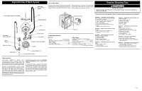
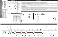
P/N: 154799901 SERVICE DATA SHEET Color Code BK Black R BU Blue VIO BU-O Blue/Orange W PK Pink R-Y Red Violet White Red/Yellow Component Checking Notes: Drain Pump: Fill Valve: Float: Detergent Dispenser: Circ Pump: Heater: 1) Always turn the timer knob clockwise. 2) Possible overshooting of the detent and gear/cam position from previous operation can affect the duration of the first interval. Toenergize, turn the timer to the detent labeled HEAVYWASH. This first interval is about 80 seconds of pump out. Turnthe timer to about 213o (labeled ìWATERTESTî in figure 1). There is a detent at this point but there is no indication of it on the console - it is for testing only. This location is the start of the final rinse.The wash segment begins with an 87 second fill. Note that the detergent dispenser is also powered during the fill. While the fill valve is energized (see above) raising the float should result in power being removed from the fill valve causing it to close. Follow instructions for energizing the fill valve. The detergent dispenser is energized during the next 179 seconds. During the first 87 seconds it runs along with the fill valve, then for 5 seconds on runs on its own and then for 87 more seconds it runs along with the circulation pump. The detergent door can be expected to open with 40 to 90 seconds of dispenser power up time. Turnthe timer to the HEAVYWASH detent and then advance about 10o further. This is starting location for about 87 seconds of circ pump actuation. WARNING! When checking that the element is giving off heat be careful not to touch the heating element inside the tub - it will burn.Tocheck for a failed heater remove power and check the resistance between the two connections. Probes can be inserted in to the back side of the connectors. The heating element changes resistance with temperature but should always be between 12 and 21 ohms.Tocheck that it is being energized by the timer, apply power to the unit and turn the timer to 303o. This angular position has a detent, is labeled HEATERTEST in figure 1 but is not labeled on the console.The detent is located at the beginning of an 87 second heating interval within the drying portion of the cycle. It is followed by several other alternating pause and heating 87 second intervals. In all, 5 heating intervals follow the detent. Wiring Diagram This information is intended for use by persons having electrical and mechanical training and a level of knowledge of these subjects generally considered acceptable in the appliance repair trade. The manufacturer or seller cannot be responsible, nor assume any liability, for injury or damage of any kind arising from the use of this Service Data Sheet. (R-Y) T.M. (BLK) (BU-O) (VIO) (PK) 0 2 4 6 8 10 (YEL/ BLK) (ORN) (BU) (R) T.M. D B C T Cycle Selection Options
-
 1
1 -
 2
2
 |
 |
