Frigidaire FCRG3052AB Installation Instructions - Page 4
Installation with cabinets
 |
View all Frigidaire FCRG3052AB manuals
Add to My Manuals
Save this manual to your list of manuals |
Page 4 highlights
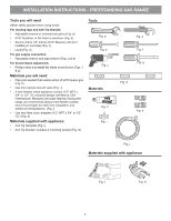
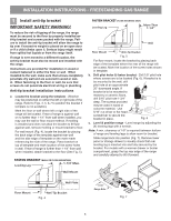
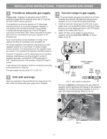
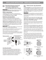
INSTALLATION INSTRUCTIONS - FREESTANDING GAS RANGE Installation with cabinets Check location where the range will be installed for proper electric and gas supply, and stability of the floor. The dimensions shown here must be used and are minimal unless otherwise stated. These measurements do not allow for any clearance below the cooking top or at the rear of the range. Contact surface must be solid and level. Things to remember: • Do not seal the range to side cabinets. • Do not pinch the power supply cord between the range and rear wall. 36" • If cabinet depth is greater than Std. 25", the oven front frame must extend beyond cabinet front by 1/2" minimum (See Fig. 1). • All openings in the wall or floor where the range is to be installed must be sealed. Installation beside wall If installing beside a wall, the minimum distance to combustible wall on either side of range above 36" height should be according to the BTU of the largest burner (See Fig 2). 18" Min. to cabinets on either side of range 13" Max. 30" 30" Min. height from cooktop to cabinets 25" 30" 11-1/2" 24" 23" *15" 10-1/2" Recommended area for thru the floor connection of gas pipe stub and shut-off valve. 2" 7" Recommended area for 120V outlet on rear of wall and area for thru the wall connection of pipe stub and shutoff valve. * Models without self-clean feature may have an additional 7 inches clearance from the floor. Fig. 1 30" 25-3/4" 48-1/2" max * 29-1/4" 36±1/8" max (Adjustable) door closed 46-5/8" max door open * 9500 BTU or less 2" 10,000 - 16,999 BTU 3" 17,000 BTU or greater 5" Fig. 2 29-7/8" Fig. 3 4
-
 1
1 -
 2
2 -
 3
3 -
 4
4 -
 5
5 -
 6
6 -
 7
7 -
 8
8 -
 9
9 -
 10
10 -
11
-
12
-
13
-
14
-
15
-
16
-
17
-
18
-
19
-
20
-
21
-
22
-
23
-
24
-
25
-
26
-
27
-
28
-
29
-
30
-
31
-
32
 |
 |
