Frigidaire FCRG3062AS Installation Instructions - Page 8
Read the following, electrical connection details, before connecting electricity, Check burner cap,
 |
View all Frigidaire FCRG3062AS manuals
Add to My Manuals
Save this manual to your list of manuals |
Page 8 highlights
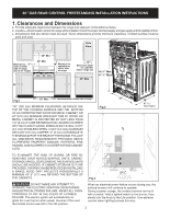
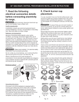
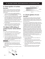
30" GAS REAR CONTROL FREESTANDING INSTALLATION INSTRUCTIONS 7. Read the following electrical connection details before connecting electricity to range. Before servicing, disconnect electrical supply at circuit breaker, fuse or power cord. Electric requirements: A dedicated, properly grounded and polarized branch circuit protected by a 15 amp. circuit breaker or time delay fuse. See serial plate for proper voltage. Extension cord precautions: Because of potential safety hazards under certain conditions, we strongly recommend against the use of any extension cord. However, if you still choose to use an extension cord, it is absolutely necessary that it be a UL listed 3-wire grounding type appliance extension cord and that the current carrying rating of the cord in amperes be equivalent to or greater than the branch circuit rating. Such extension cords are obtainable through your local service organization. Please read carefully! For personal safety, this product must be properly grounded. Do not, under any circumstances, cut or remove the third (ground) prong from the power cord (See Fig. 12). Where a standard two-prong wall receptacle is encountered, it is the personal responsibility and obligation of the customer to have it replaced with a properly grounded three-prong wall receptacle. Preferred method Grounding type wall receptacle Do not, under any circumstances, cut, remove or bypass the grounding prong. Fig. 12 Power supply cord with 3-prong grounding plug 8. Check burner cap placement. It is very important to be sure that all surface burner caps and burner grates are properly installed and in the correct locations before operating the appliance. The cooktop is not removeable. Do not attempt to remove or lift the cooktop. To prevent flare-ups and avoid creation of harmful by-products, do not use the cooktop without all burner caps properly installed to insure proper ignition and gas flame size. Always keep the burner caps and burner heads in place whenever the surface burners are in use. Do not allow spills, food, cleaning agents or any other material to enter the gas orifice holder openings. Check and be sure the size of each burner cap matches the size of the burner head. Check and be sure that all round style burner caps are correctly in place on round burner heads. Check and be sure that all oval style burner caps are correctly in place on oval burner heads (if equipped). Check and be sure that all dual or twin style burner caps are correctly in place on dual or twin burner heads (if equipped). On round style burners, the burner cap lip (See Fig. 13) should fit snug into the center of burner head and be level. Refer to Figs. 14 & 15 for correct and incorrect burner cap placement. Once in place, you may check the fit by gently sliding the burner cap from side to side (Fig. 16) to be sure it is centered and firmly seated. Please note that the burner cap should NOT move off the center of the burner head when sliding from side to side. Fig. 13 - Burner styles Grounding instructions: The power cord of this appliance is equipped with a 3-prong (grounding) plug which mates with a standard 3-prong grounding wall receptacle to minimize the possibility of electric shock hazard from this appliance. The customer should have the wall receptacle and circuit checked by a qualified electrician to make sure the Correct burner Incorrect burner cap placement cap placement receptacle is properly grounded and polarized. Fig. 14 Fig. 15 8 Fig. 13 Fig. 16
-
 1
1 -
2
-
 3
3 -
 4
4 -
 5
5 -
 6
6 -
 7
7 -
 8
8 -
 9
9 -
 10
10 -
 11
11 -
 12
12 -
 13
13 -
14
-
15
-
16
-
17
-
18
-
19
-
20
-
21
-
22
-
23
-
24
-
25
-
26
-
27
-
28
-
29
-
30
-
31
-
32
 |
 |
