Frigidaire FDB520RHS Installation Instructions (English) - Page 2

Finishing the Electrical - dishwasher

Page 2 highlights

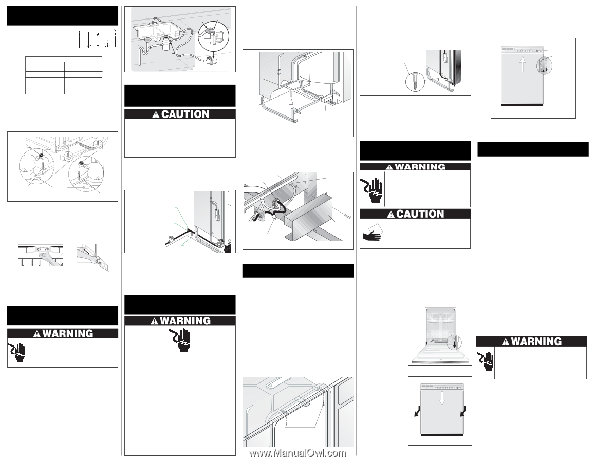
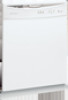
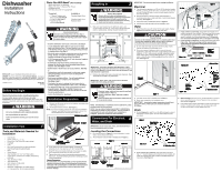
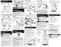
Leveling Dishwasher 5 within Cabinets 1. Measure height of cabinet opening from underside of countertop to floor. Check chart for height opening and suggested adjustment. Leg Leveler Adjustment Chart Height of Cabinet Opening Number of Turns to Adjust Levelers 34" (86.4cm) 0 341/8" (86.7cm) 2 345/16" (87.2cm) 6 341/2" (87.6cm) 9 For additional height add shims under levelers. 2. Move dishwasher to front of installation area. 3. Loosen the front and rear leveling legs by turning counterclockwise. Refer to chart for number of turns. See Figure 8. Front levelers should allow 1/4" below underside of countertop. S o c5/k3e2"t 5/32" Socket Front Leveler Figure 8 15/16" Wrench Rear Leveler 4. If levelers have to be removed, make sure floor is free of obstructions. 5. Place dishwasher inside cabinet area so that it is centered in opening. Use caution when moving dishwasher to prevent damage to dishwasher, floor, and cabinets. 6. Check that dishwasher is level from side to side by placing a level against the top front section of the tub. See Figure 9a. Figure 9a Figure 9b 7. Check that dishwasher is level from front to back by placing level on side of opened door. See Figure 9b. 8. Adjust levelers up or down until dishwasher is level. Finishing the Drain 6 Connection Sink at Left Connector 32" Clamp Remove kpnluogckinout disposer Pump Motor Figure 10 The drain hose loop must be at least 32" high from the floor to insure proper drainage. Finishing the Water 7 Connection Property Damage Do not solder within 6" of the water inlet valve. Damage to the plastic parts in the valve may occur. Use care that no sealer, dirt, or other objects enter the valve. Damage to the filter screen may occur. Be sure the dishwasher is placed where the water inlet valve will be kept from freezing. If the valve freezes, it may rupture and flooding may occur. Water Line 1. Flush water line before connecting it to water inlet valve to prevent early clogging of filter screen. Place a bunched towel over end of line to prevent splashing. Open water supply valve for a few seconds and let water drain into a pan. Turn off water supply at shut-off valve. Figure 11 Through Wall Through Cabinet Through Floor 2. Route water line to water inlet valve as shown in Figure 11. 3. While firmly pulling water supply line into 90° elbow, tightly connect water supply to water inlet valve. Supply line must be free of kinks, scales, chips, and lubricants. 4. Turn on water supply and check for leaks. 5. If water inlet valve clogs, make sure water supply is off. Remove four (4) screws at inlet end of valve and clean filter screen. Finishing the Electrical 8 Connection Electric Shock Hazard Plumbing material and drain hose must not come in contact with wiring or electrical components. Failure to follow this warning could result in personal injury from exposed wiring. 1. Pull out unit and check to see if drain hose is correctly attached to the drain pump assembly. If drain hose is not attached to drain pump, follow the instruction sheet (included with drain hose) on how to correctly install the drain hose to the drain pump assembly. 2. Move unit back in place while routing drain hose through access hole. Use caution to prevent damage to the dishwasher, floor and cabinets. IMPORTANT: Make sure there are no sharp bends or kinks that might restrict drain flow. 3. Secure drain hose to sink drain, disposer, or separate trap with a clamp. IMPORTANT: Be careful not to overtighten clamp or you may damage end of hose. Do not connect hose to horizontal pipe between sink drain and disposer. 4. Be sure unit does not rest on drain hose. It should be free of electrical components and door springs. Do not cut corrugated drain hose. Pull excess through cabinet and place under sink. Make sure hose does not come in contact with any sharp edges. See Figure 10. Electric Shock Hazard Make sure electrical power has been disconnected at fuse box or circuit breaker box. The dishwasher must be connected to a grounded metal, permanent wiring system. The equipment-grounding conductor must be run with the circuit conductors and connected to the appliance's equipment grounding terminal or lead. It is the consumer's responsibility to contact a qualified installer to make sure the electrical installation conforms with the National Electrical Code and local codes and ordinances. Do not connect the dishwasher to the power supply until the appliance is permanently grounded. All wiring connections must be enclosed in the junction box. This unit has copper lead wires. Joining aluminum building wire to stranded copper wire should be done by a qualified electrician using materials recognized by UL and local codes. Do not use an extension cord. Such use can result in fire, electrical shock, or other personal injury. Failure to follow these instructions could result in death or serious injury. Electrical Supply 1. Remove junction box cover and pull house wiring into junction box. See Figures 12 and 13. 2. Use a UL listed conduit connector,(not included), at box to stabilize wiring. IMPORTANT: Be sure electrical cable is not routed behind dishwasher's motor. Floor Anchoring This procedure is difficult and should be used only if countertop mounting brackets cannot be used. 1. Screw 1/4" lag screws, (not included), through holes provided in frame rail. See Figure 15. 2. Use expansion fasteners if floor is concrete. Before starting the dishwasher, Through Wall Through Cabinet Use (not 1i/n4c"luLdaegdS)crews Figure 15 Through Floor Junction Box (in place) Figure 12 3. Inside junction box, attach ground wire under head of grounding screw and tighten. See Figure 13. 4. Connect incoming black lead to dishwasher's black lead and incoming white lead to dishwasher's white lead with wire nuts or other suitable connectors,(not included). Wire nuts should be tight. Note: If mounting your dishwasher to the countertop or to the floor is not a desirable option, you can order the side mount kit, 154477201, by contacting your dealer or parts supplier. This allows you to install the dishwasher by securing it to the cabinets or partitions on either side of the unit. The kit utilizes the front frame of the dishwasher to secure the unit to the cabinet or partitions. Installing Wood Panel 10 Removing & Replacing Door Conduit Connector (not included) Ground Wire Electric Shock Hazard Disconnect electrical power at the fuse box or circuit breaker box before beginning installation. Failure to follow this warning could result in death or serious injury. WWhhiittee WWiirree to (Neutral) Black Wire to Black Wire (Hot) Figure 13 5. Replace junction box cover. See Figure 13. Junction Box Cover 10 Securing the Dishwasher 9 The dishwasher must be secured to keep it from tilting when door is opened. Choose one of the methods described below to secure unit. Countertop Anchoring 1. Install the Cabinet Seal Kit (Instructions included in Kit) 2. Replace Kickplate. See Figure 1 3. Adjust levelers (see Step 5) so mounting brackets touch underside of countertop. IMPORTANT: Dishwasher must rest on floor-do not hang from countertop. See Figure 14. 4. Tub needs to be even with the front of adjoining cabinets. 5. Screw mounting brackets firmly to countertop using screws provided in literature packet. 6. Open and close dishwasher door slowly. If door hits mounting brackets lower the dishwasher in front and rear. Note: Open and close door to make sure it does not hit surrounding cabinets or countertop. Cut Hazard Metal color panels are sharp and should be handled with care. Wear gloves to protect hands. Failure to follow this warning may result in injury. To Install a Custom Wood Panel The dishwasher door panel can be customized to match wood cabinets. This will require a kit that includes a mid-door with side and bottom trim, heavy-duty door springs and instructions. Kits are available from your dealer or parts supplier. Note: Custom Wood Panels are not available on 1000 Series and 4000 Series Dishwashers. To Remove and Replace Outer Door 1. Unlatch and open door. Using a Phillips head screw driver, remove two (2) screws from inner door. Save screws to reassemble. See Figure 16a. Figure 16a 2. Close and latch door while holding both sides. 3. Place one hand on each side of door and pull down at top approximately 1/4". Pull entire door assembly toward you to remove. See Figure 16b. Figure 16b 4. Place door where it will not get scratched or damaged while completing installation. 5. When ready to replace door, fit the slots on each side of top door edge over the tabs on the metal liner. Push on sides to insure the door is flat. Push up from bottom until there is no gap between door and console. See Figure 16c. Figure 16c Console Metal Liner Door Side View Appearance of console and door may vary from your model. 6. Unlatch door and open while supporting outer door on both sides at bottom to keep in place. Align screw holes and replace screws. Checking the Installation 11 check these items: q Drain hose is assembled to drain pump. q All packing materials and consumer literature have been removed from unit. q Dishwasher is level and securely fastened. q Open and close door to make sure it does not hit surrounding cabinet or countertop. q Water and drain lines have no kinks. q Wiring connections to junction box are tight. q Water supply is turned on. q Joints are free of leaks. Replacing Door 1. Refer to Step 10, numbers 5 and 6, for replacing outer door. 2. Adjust door springs to balance weight of door. A correct spring setting allows door to remain horizontal in opened position, yet will rise to close with slight lift of finger. 3. If necessary, increase tension by moving springs to a hole toward rear of unit or decrease by moving them toward front. 4. Turn electrical supply on. Operate the machine through at least one fill and pump-out, checking the following items: q At first fill, make sure water completely covers filter surface. (Motor pump sound may be heard before water enters unit). q At pump-out, make sure all water is pumped out. q Check water connections again for leaks. Electric Shock Hazard If all connections are correct, there are no leaks, and unit runs properly, replace the kickplate assembly before placing unit into operation. Failure to follow this warning could result in electric shock. Use Phillips Head Screws # 8 x 5/8" (included in the literature packet). Figure 14 Appearance of console and door may vary from your model.

  • 1
  • 2

1.
Measure height of cabinet opening
from underside of countertop to floor.
Check chart for height opening and
suggested adjustment.
2.
Move dishwasher to front of installation area.
3.
Loosen the front and rear leveling legs by turning
counterclockwise. Refer to chart for number of turns.
See
Figure 8.
Front levelers should allow
1
/
4
” below underside of
countertop.
5
Leveling Dishwasher
within Cabinets
Number of Turns to
Adjust Levelers
Height of
Cabinet Opening
Leg Leveler Adjustment Chart
34
1
/
8
” (86.7cm)
34
5
/
16
” (87.2cm)
0
2
6
9
For additional height add shims under levelers.
4.
If levelers have to be removed, make sure floor is free of
obstructions.
5.
Place dishwasher inside cabinet area so that it is centered in
opening. Use caution when moving dishwasher to prevent
damage to dishwasher, floor, and cabinets.
6.
Check that dishwasher is level from side to side by placing a
level against the top front section of the tub.
See Figure 9a.
Figure 8
Figure 8
Figure 8
Figure 8
Figure 8
5
5
5
5
5
/
32
32
32
32
32
Socket
Socket
Socket
Socket
Socket
Socket
Socket
Socket
Socket
Socket
Rear Leveler
Rear Leveler
Rear Leveler
Rear Leveler
Rear Leveler
Wrench
Wrench
Wrench
Wrench
Wrench
Front Leveler
Front Leveler
Front Leveler
Front Leveler
Front Leveler
Figure 10
Figure 10
Figure 10
Figure 10
Figure 10
7
Finishing the Water
Connection
Property Damage
Do not solder within 6” of the water inlet valve. Damage to
the plastic parts in the valve may occur.
Use care that no sealer, dirt, or other objects enter the valve.
Damage to the filter screen may occur.
Be sure the dishwasher is placed where the water inlet valve
will be kept from freezing. If the valve freezes, it may rupture
and flooding may occur.
Water Line
1.
Flush water line before connecting it to water inlet valve to
prevent early clogging of filter screen.
Place a bunched towel
over end of line to prevent splashing. Open water supply valve for
a few seconds and let water drain into a pan.
Turn off water
supply
at shut-off valve.
Through
Through
Through
Through
Through
Wall
Wall
Wall
Wall
Wall
Through
Through
Through
Through
Through
Cabinet
Cabinet
Cabinet
Cabinet
Cabinet
Figure 11
Figure 11
Figure 11
Figure 11
Figure 11
1.
Remove junction box cover and pull house wiring into junction
box.
See Figures 12 and 13.
2.
Use a UL listed conduit connector,(not included), at box to
stabilize wiring.
IMPORTANT:
Be sure electrical cable is not routed behind
dishwasher’s motor.
Electrical Supply
Conduit
Conduit
Conduit
Conduit
Conduit
Connector
Connector
Connector
Connector
Connector
(not included)
(not included)
(not included)
(not included)
(not included)
Ground Wire
Ground Wire
Ground Wire
Ground Wire
Ground Wire
Through
Through
Through
Through
Through
Wall
Wall
Wall
Wall
Wall
Through
Through
Through
Through
Through
Cabinet
Cabinet
Cabinet
Cabinet
Cabinet
Junction Box
Junction Box
Junction Box
Junction Box
Junction Box
(in place)
(in place)
(in place)
(in place)
(in place)
Through
Through
Through
Through
Through
Floor
Floor
Floor
Floor
Floor
Figure 12
Figure 12
Figure 12
Figure 12
Figure 12
Floor Anchoring
This procedure is difficult and should be used only if countertop
mounting brackets cannot be used.
1.
Screw
1
/
4
” lag screws, (not included), through holes provided in
frame rail.
See Figure 15.
2.
Use expansion fasteners if floor is concrete.
Before starting the dishwasher,
Figure 15
Figure 15
Figure 15
Figure 15
Figure 15
Use
Use
Use
Use
Use
1
/
4
” Lag Screws
” Lag Screws
” Lag Screws
” Lag Screws
” Lag Screws
(not included)
(not included)
(not included)
(not included)
(not included)
10
The dishwasher door panel can be customized to match wood
cabinets. This will require a kit that includes a mid-door with side
and bottom trim, heavy-duty door springs and instructions.
Kits are available from your dealer or parts supplier.
Note:
Custom Wood Panels are not available on 1000 Series and
4000 Series Dishwashers.
Cut Hazard
Electric Shock Hazard
Disconnect electrical power at the fuse box
or circuit breaker box before beginning
installation.
Failure to follow this warning could result in
death or serious injury
.
Metal color panels are sharp and should be
handled with care. Wear gloves to protect
hands.
Failure to follow this warning may result in
injury.
Installing Wood Panel
Removing & Replacing Door
To Install a Custom Wood Panel
Side
Side
Side
Side
Side
View
View
View
View
View
Figure 16c
Figure 16c
Figure 16c
Figure 16c
Figure 16c
Console
Metal
Liner
Door
Checking the Installation
11
check these items:
q
Drain hose is assembled to drain pump.
q
All packing materials and consumer literature have been
removed from unit.
q
Dishwasher is level and securely fastened.
q
Open and close door to make sure it does not hit
surrounding cabinet or countertop.
q
Water and drain lines have no kinks.
q
Wiring connections to junction box are tight.
q
Water supply is turned on.
q
Joints are free of leaks.
34” (86.4cm)
34
1
/
2
” (87.6cm)
The drain hose loop must be at least 32” high from the floor
to insure proper drainage.
3.
Inside junction box, attach ground wire under head of grounding
screw and tighten.
See Figure 13.
4.
Connect incoming black lead to dishwasher’s black lead and
incoming white lead to dishwasher’s white lead with wire nuts or
other suitable connectors,(not included). Wire nuts should be
tight.
4.
Place door where it will not get scratched or damaged while
completing installation.
5.
When ready to replace door, fit the slots on each side of top
door edge over the tabs on the metal liner. Push on sides to
insure the door is flat. Push up from bottom until there is no gap
between door and console.
See Figure 16c.
6.
Unlatch door and open while supporting outer door on both sides
at bottom to keep in place. Align screw holes and replace
screws.
Appearance of console and door may
vary from your model.
Remove
Remove
Remove
Remove
Remove
knockout
knockout
knockout
knockout
knockout
plug in
plug in
plug in
plug in
plug in
disposer
disposer
disposer
disposer
disposer
Pump Motor
Pump Motor
Pump Motor
Pump Motor
Pump Motor
Clamp
Clamp
Clamp
Clamp
Clamp
Connector
Connector
Connector
Connector
Connector
Sink at Left
Sink at Left
Sink at Left
Sink at Left
Sink at Left
32”
32”
32”
32”
32”
1.
Unlatch and open
door. Using a Phillips
head screw driver,
remove two (2) screws
from inner door. Save
screws to reassemble.
See
Figure 16a
.
2.
Close and latch door
while holding both
sides.
3.
Place one hand on
each side of door and
pull down at top
approximately
1
/
4
”.
Pull entire door
assembly toward
6
Finishing the Drain
Connection
Electric Shock Hazard
Plumbing material and drain hose must not come
in contact with wiring or electrical components.
Failure to follow this warning could result in
personal injury from exposed wiring.
1.
Pull out unit and check to see if drain hose is correctly attached
to the drain pump assembly. If drain hose
is not attached
to
drain pump, follow the instruction sheet (included with drain
hose) on how to correctly install the drain hose to the drain pump
assembly.
2.
Move unit back in place while routing drain hose through access
hole. Use caution to prevent damage to the dishwasher, floor
and cabinets.
IMPORTANT: Make sure there are no sharp
bends or kinks that might restrict drain flow.
3.
Secure drain hose to sink drain, disposer, or separate trap with a
clamp.
IMPORTANT:
Be careful not to overtighten clamp or
you may damage end of hose.
Do not connect hose to
horizontal pipe between sink drain and disposer.
4.
Be sure unit does not rest on drain hose. It should be free of
electrical components and door springs. Do not cut corrugated
drain hose.
Pull excess through cabinet and place under sink.
Make sure hose does not come in contact with any sharp edges.
See Figure 10.
Through
Through
Through
Through
Through
Floor
Floor
Floor
Floor
Floor
2.
Route water line to water inlet valve as shown in
Figure 11.
3.
While firmly pulling water supply line into 90
°
elbow, tightly
connect water supply to water inlet valve. Supply line must be
free of kinks, scales, chips, and lubricants.
4.
Turn on water supply and check for leaks.
5
.
If water inlet valve clogs, make sure water supply is off.
Remove four (4) screws at inlet end of valve and clean filter
screen.
Finishing the Electrical
Connection
8
Electric Shock Hazard
Make sure electrical power has been disconnected at fuse
box or circuit breaker box.
The dishwasher must be connected to a grounded metal,
permanent wiring system. The equipment-grounding
conductor must be run with the circuit conductors and
connected to the appliance’s equipment grounding terminal
or lead. It is the consumer’s responsibility to contact a
qualified installer to make sure the electrical installation
conforms with the National Electrical Code and local codes
and ordinances.
Do not connect the dishwasher to the power supply until the
appliance is permanently grounded.
All wiring connections must be enclosed in the junction box.
This unit has copper lead wires.
Joining aluminum building wire to stranded copper wire
should be done by a qualified electrician using materials
recognized by UL and local codes.
Do not use an extension cord. Such use can result in fire,
electrical shock, or other personal injury.
Failure to follow these instructions could result in death or
serious injury.
Figure 13
Figure 13
Figure 13
Figure 13
Figure 13
White Wire to
White Wire to
White Wire to
White Wire to
White Wire to
White Wire
White Wire
White Wire
White Wire
White Wire
(Neutral)
(Neutral)
(Neutral)
(Neutral)
(Neutral)
Black Wire to
Black Wire to
Black Wire to
Black Wire to
Black Wire to
Black Wire (Hot)
Black Wire (Hot)
Black Wire (Hot)
Black Wire (Hot)
Black Wire (Hot)
Junction
Junction
Junction
Junction
Junction
Box Cover
Box Cover
Box Cover
Box Cover
Box Cover
10
The dishwasher must be secured to keep it from tilting when door is
opened. Choose one of the methods described below to secure unit.
Countertop Anchoring
1.
Install the Cabinet Seal Kit (Instructions included in Kit)
2.
Replace Kickplate.
See Figure 1
3.
Adjust levelers (see Step 5)
so mounting brackets touch
underside of countertop. IMPORTANT: Dishwasher must rest on
floor—do not hang from countertop. See Figure 14.
4.
Tub needs to be even with the front of adjoining cabinets.
5.
Screw mounting brackets firmly to countertop using screws
provided in literature packet.
6.
Open and close dishwasher door slowly. If door hits mounting
brackets lower the dishwasher in front and rear.
Securing the Dishwasher
9
Use Phillips Head Screws
# 8 x
# 8 x
# 8 x
# 8 x
# 8 x
5
/
8
” (included in the
” (included in the
” (included in the
” (included in the
” (included in the
literature packet).
literature packet).
literature packet).
literature packet).
literature packet).
Figure 14
Figure 14
Figure 14
Figure 14
Figure 14
To Remove and Replace Outer Door
Operate the machine through at
least one fill and pump-out,
checking the following items:
q
At first fill, make sure water completely covers filter surface.
(Motor pump sound may be heard before water enters unit).
q
At pump-out, make sure all water is pumped out.
q
Check water connections again for leaks.
Electric Shock Hazard
If all connections are correct, there are no leaks,
and unit runs properly, replace the kickplate
assembly before placing unit into operation.
Failure to follow this warning could result in
electric shock.
1.
Refer to
Step 10
, numbers 5 and 6, for replacing outer door.
2.
Adjust door springs to balance weight of door. A correct spring
setting allows door to remain horizontal in opened position, yet
will rise to close with slight lift of finger.
3.
If necessary, increase tension by moving springs to a hole
toward rear of unit or decrease by moving them toward front.
4.
Turn electrical supply on.
Replacing Door
7.
Check that dishwasher is level from front to back by placing
level on side of opened door.
See Figure 9b.
8.
Adjust levelers up or down until dishwasher is level.
Figure 9b
Figure 9b
Figure 9b
Figure 9b
Figure 9b
Figure 9a
Figure 9a
Figure 9a
Figure 9a
Figure 9a
Figure 16a
Figure 16a
Figure 16a
Figure 16a
Figure 16a
Figure 16b
Figure 16b
Figure 16b
Figure 16b
Figure 16b
Appearance of console and door may
vary from your model.
5.
Replace junction box cover.
See Figure 13.
Note:
If mounting your dishwasher to the
countertop or to the floor is not a desirable option,
you can order the side mount kit, 154477201, by
contacting your dealer or parts supplier.
This allows
you to install the dishwasher by securing it to the
cabinets or partitions on either side of the unit.
The
kit utilizes the front frame of the dishwasher to
secure the unit to the cabinet or partitions.
5
5
5
5
5
/
32
32
32
32
32
you to remove.
See Figure 16b
.
Note:
Open and close door to make sure it does not hit
surrounding cabinets or countertop.
15
15
15
15
15
/
16
16
16
16
16