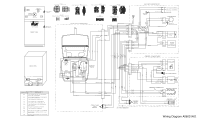
Frigidaire FFHI1832TS Wiring Diagram
Frigidaire FFHI1832TS Manual
 |
View all Frigidaire FFHI1832TS manuals
Add to My Manuals
Save this manual to your list of manuals |
Frigidaire FFHI1832TS manual content summary:
- Frigidaire FFHI1832TS | Wiring Diagram - Page 1
35% Freezer Temperature 2° to 8°F (-17° to -13°C) Refrigerator Temperature 35° to 40°F (2° to 4°C) Low Side Pressure (cut 3 Black 4 Light Blue SERVICE DATA SHEET A06813801 STANDARD - switch 5 times in 6 seconds. CAUTION All electrical parts and wiring must be shielded from torch flame. DO - Frigidaire FFHI1832TS | Wiring Diagram - Page 2
MC2/FF1 JST VLR-09 JST VLP-09 I M C FZ1 DEFROST THERMOSTAT EFC DH1 EVAP FAN DH2 FREEZER DOOR SWITCH 1 1 DH1/DH2 MOLEX 19-09-2019 MOLEX 19-09-1019 IMC TYCO 1-480702-0 TYCO 1-480703-0 1 1 FF1 CONTROL BOX FRESH FOOD DOOR SWITCH FRESH FOOD COMPARTMENT FRONT VIEW EFC/CFC TYCO 1-
-
 1
1 -
 2
2
 |
 |
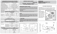
SERVICE DATA SHEET
A06813801
STANDARD - AUTOMATIC DEFROST
TOP MOUNT FREEZER - R134a
IMPORTANT SAFETY NOTE
The information provided herein is designed to assist qualified repair
personnel only. Untrained persons should not attempt to make repairs
due to the possibility of electrical shock. Disconnect power cord before
servicing this appliance.
IMPORTANT
If any green grounding wires are removed during servicing, they must
be returned to their original position and properly secured.
CAUTION
All electrical parts and wiring must be shielded from torch flame.
DO NOT allow torch to touch insulation; it will char at 200°F
and flash ignite (burn) at 500°F. Excessive heat will distort the
plastic liner.
NOTE
Some products come equipped with an Electronic Defrost Control. To
initiate defrost, depress the fresh food light switch 5 times in 6 seconds
(light bulb must be working). To terminate defrost, depress the fresh
food light switch 5 times in 6 seconds.
BLUE
YELLOW
YELLOW
BLUE
BLUE
DK. BLUE
BLUE
ICE MAKER INFORMATION
PERFORMANCE DATA NO LOAD & NO DOOR
OPENINGS AT MID-POINT CONTROL SETTING
Capacitor Run or Induction Run
65°F (18°C) Ambient
Operating Time
25 to 35%
Freezer Temperature
2° to 8°F (-17° to -13°C)
Refrigerator Temperature
35° to 40°F (2° to 4°C)
Low Side Pressure (cut-in)
8 to 16 psig
( 55 to 110 kPa)
Low Side Pressure (cut-out)
1 to 4 psig (7 to 28 kPa)
High Side Pressure (last 1/3 cycle)
110 to 120 psig
(758 to 827 kPa)
Wattage (last 1/3 cycle)
95 to 140
Amps (running)
0.9 to 1.3
Base Voltage
115 vac (127 vac max)
DEFROST SPECIFICATIONS
Cabinet Size
Thermostat
Cut-in
Cut-out
Ohms
18’, 20’ & 21’
9°F (-2°C)
50°F (10°C)
35
15’ & 16’
29°F (-2°C)
50°F (10°C)
41
Mechanical Timer - Defrost 24 minutes every 10 hours of compressor
run time.
Electronic Timer (ADC) - Defrost up to 24 minutes every 6-72 hours of
compressor run time.
CONDENSER FAN MOTOR
Watts
RPM
2.3
1100 CW Opposite Shaft
ICE MAKER SPECIFICATIONS
Electrical
115 vac (127
vac max)
60 Hertz
Thermostat
Ice maker with
black housing
Opens at 52°F
(11°C)
Closes at 12°F
(-11°C)
Ice maker with
white housing
Opens at 48°F
(8.9°C)
Closes at 9°F
(-12.8°C)
Heater Wattage
165 W
ICE MAKER CONNECTOR PLUG CONNECTIONS
Wire Number
Wire Color
1
Green / Yellow
2
Yellow
3
Black
4
Light Blue
IMPORTANT
PLEASE RETURN THIS SHEET TO ITS
ORIGINAL LOCATION.
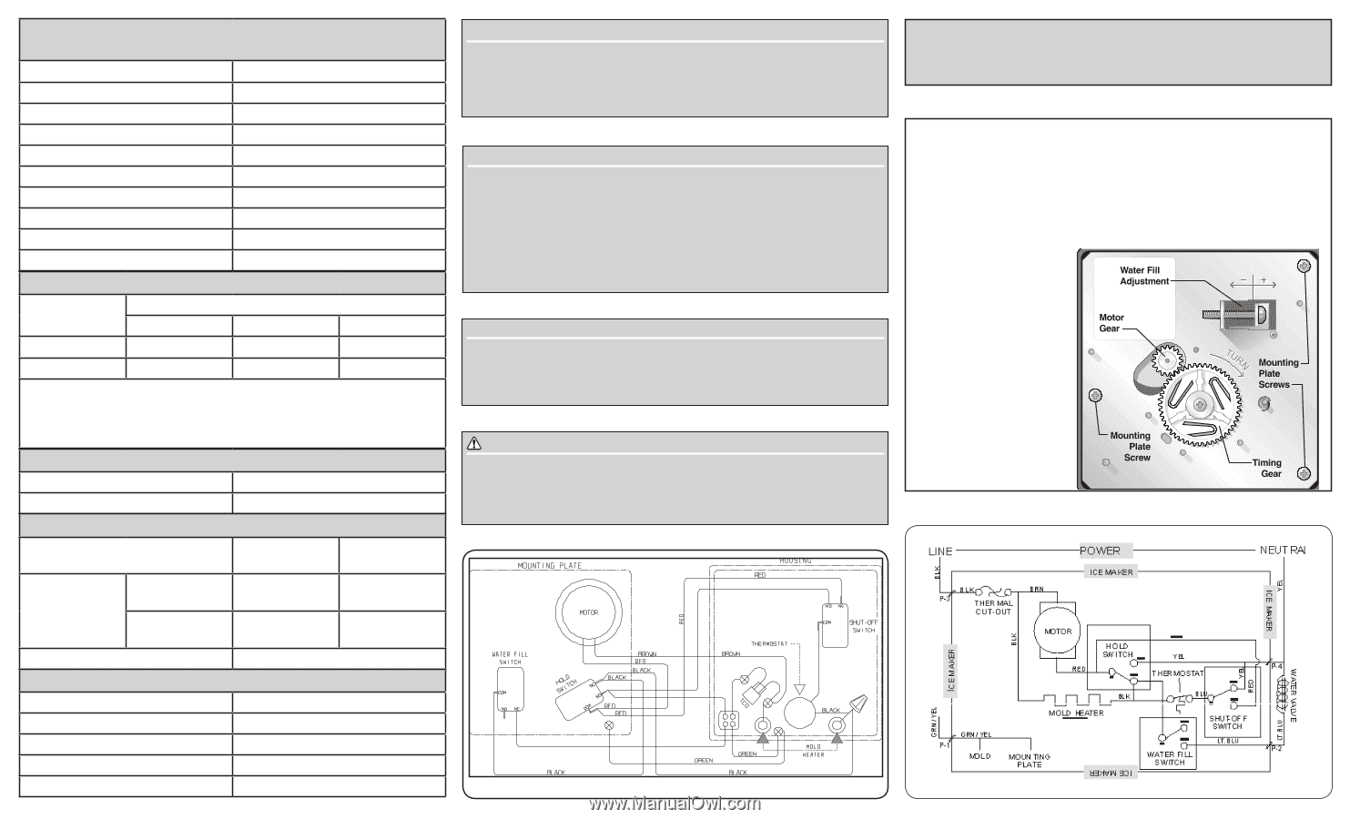
Test Cycling:
Remove cover by inserting screwdriver in notch at
bottom and prying cover from housing. Use screwdriver to rotate
motor gear counterclockwise until holding switch circuit is com-
pleted. All components of ice maker should function to complete
the cycle.
Water Fill Volume:
The water fill adjustment
screw will change the
fill time. One full turn is
equal to 20cc (.68 oz.).
The correct fill is 102 to
130cc (3.4 to 4.3 oz.).
When a water valve is
replaced, the fill volume
must be checked.