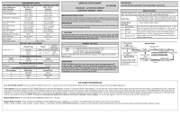
Frigidaire FFHT1425VW Wiring Diagram - Page 1
Frigidaire FFHT1425VW Manual
 |
View all Frigidaire FFHT1425VW manuals
Add to My Manuals
Save this manual to your list of manuals |
Page 1 highlights
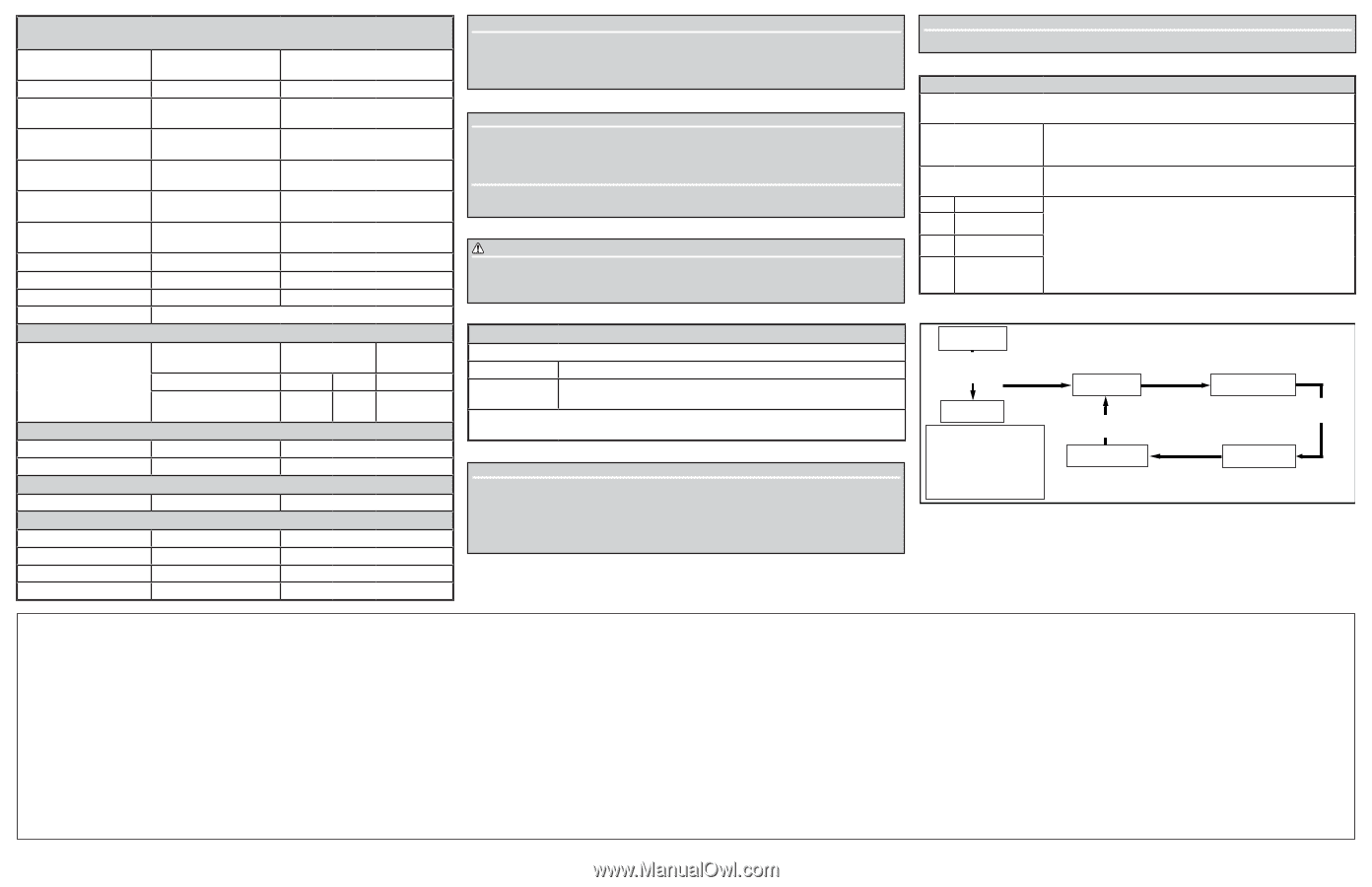
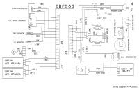
PERFORMANCE DATA NO LOAD & NO DOOR OPENINGS AT MID-POINT CONTROL SETTING Type A With Run/ Start Capacitor 70°F (21.1°C) Ambient 90°F (32°C) Ambient Operating Time 26 to 29% 45 to 47% Freezer Temperature 5° to -2.2°F (-15° to -19°C) 5° to -2.2°F (-15° to -19°C) Refrigerator Temperature 35° to 40°F (2° to 4°C) 35° to 40°F (2° to 4°C) Low Side Pressure (cut-in) -3.24 to 0.80 psig ( 79 to 107 kPa) -3.24 to -0.66 psig (79 to 97 kPa) Low Side Pressure (cut-out) -6.70 to -6.19 psig (55 to 59 kPa) -6.59 to -6.22 psig (56 to 58 kPa) High Side Pressure (last 1/3 cycle) 38 to 39 psig (364 to 372 kPa) 57 to 58 psig (498 to 503 kPa) Wattage (last 1/3 cycle) 68 W 68 W Amps (running) 0.6 to 0.8 A 0.6 to 0.8 A Base Voltage 115 V 115 V Refrigerant Charge 1.58 oz. (45 g) DEFROST SPECIFICATIONS Thermal Fuse Heater Defrost Thermistor Cabinet Size: 14' Cut-out Watts Ohms Termination 161.6°F (72°C) 166 79.7 48°F (8.89°C) EVAPORATOR FAN MOTOR Watts RPM Amps 3.1 (max) 2700 CW 0.258 Running ICE MAKER SPECIFICATIONS Electrical 115 vac (127 vac max) 60 Hertz ICE MAKER CONNECTOR PLUG CONNECTIONS Wire Number Wire Color Connects to: 1 Light Blue Neutral 2 Yellow Water Valve 3 Black Line SERVICE DATA SHEET STANDARD - AUTOMATIC DEFROST TOP MOUNT FREEZER - R600a A17276301 IMPORTANT SAFETY NOTE The information provided herein is designed to assist qualified repair personnel only. Untrained persons should not attempt to make repairs due to the possibility of electrical shock. Disconnect power cord before servicing this appliance. IMPORTANT If any green grounding wires are removed during servicing, they must be returned to their original position and properly secured. CAUTION All electrical parts and wiring must be shielded from torch flame. DO NOT allow torch to touch insulation; it will char at 200°F and flash ignite (burn) at 500°F. Excessive heat will distort the plastic liner. IMPORTANT PLEASE RETURN THIS SHEET TO ITS ORIGINAL LOCATION. SERVICE MODE SERVICE MODE will step through available tests to diagnose individual electrical circuits. Fresh Food compartment light will be OFF while in SERVICE MODE. enter/exit --> Press the door switch 3 times and hold the 4th press until the FF light turns on. When switch is released the light should turn off. The door switch must be pressed 4 times in 2 seconds. initiate first/ next test --> Press the door switch 2 times. 1 Compressor Press the FF door switch twice to start the first test. In each 2 Heater test, the component listed will be powered on. The component will stay powered until the next test is activated, or until 3 FF Light 5 minutes of inactivity expire. Listen for operating sounds; feel for heat or air flow, as appropriate, to determine the 4 Evaporator Fan result of each test. Press the FF door switch twice again to advance between tests. MANUAL DEFROST Unit will complete normal defrost cycle. enter --> Press the FF door switch 5 times in 2 secs. exit --> Cycle power to the unit or enter and exit SERVICE MODE. (See SERVICE MODE) Defrost is terminated when defrost thermistor located on the evaporator coil reaches 48°F (8.89°C). IMPORTANT START-UP NOTE: Upon 1st start-up or power cycle, the compressor will come on after 15 seconds and run for 4 minutes. If the door switch is not cycled during this time, the compressor may cut off after 4 minutes and not turn back on for another 3 minutes. It may take up to 10 minutes for the compressor to turn on and run in normal mode. Normal Cooling Service Mode Mode Press Door Switch 3 Press Door Switch Times and Hold 4th Press Until 2 Times the FF Light Turns On Test 1: Test 2: Power ON Press Door Switch Compressor ON Enters Service 2 Times Mode Press Door Switch Manual Defrost 2 Times to Defrost Heater To Exit Service Mode from Press Door Switch any Test Press Door Switch 2 Times 3 Times and Hold 4th Press Press Door Switch 5 Times to Enter Manual Defrost. POR or Enter Service Mode to Exit Manual Defrost. Test 4: Evaporator Test 3: Fresh Fan ON Press Door Switch Food Light ON 2 Times 108 mm ICE MAKER INFORMATION Turn the IM ON and OFF: Press and hold the POWER button for ½ second to turn the IM ON and OFF. When the IM is ON, the Power button will be illuminated solid green Test Cycling: Press and release the TEST/SERVICEbutton to start the self-diagnostic function. The tray will perform two rotations. The ice level arm must be held so that it does not drop during the first rotation (simulating full ice bin). Once the tray returns to the Home position, the arm can be released. Allow the arm to drop normally during the the second rotation (simulating empty ice bin). Once the tray returns Home after the second rotation, the POWER button will change back to solid green if no errors were detected during the test. This means the IM operates properly. If errors are detected at any time during the test, the test will stop immediately and the POWER button will blink rapidly continuously. In this case, there is some internal failure of the IM. NOTE: If the arm is not held during the first rotation, the IM will indicate a failure falsely. To run the test again to verify, the IM must be turned OFF and back ON. Manual Water Fill: Press and hold the TEST/SERVICE button for 3+ seconds. Adjust Water Fill Size: Press and hold the POWER and TEST/SERVICE buttons together for 3 seconds. The POWER button will blink to show the current setting. 1 blink = small, 2 blinks = med, 3 blinks = large, 4 blinks = extra large. Press the TEST/SERVICE button to advance to the next level. When at extra large, the next press goes back to small. The factory default is small.
-
 1
1 -
 2
2
 |
 |