Frigidaire FGEF3056KF Wiring Diagram (All Languages) - Page 1
Frigidaire FGEF3056KF - Gallery Series Electric Range Manual
 |
UPC - 012505500466
View all Frigidaire FGEF3056KF manuals
Add to My Manuals
Save this manual to your list of manuals |
Page 1 highlights
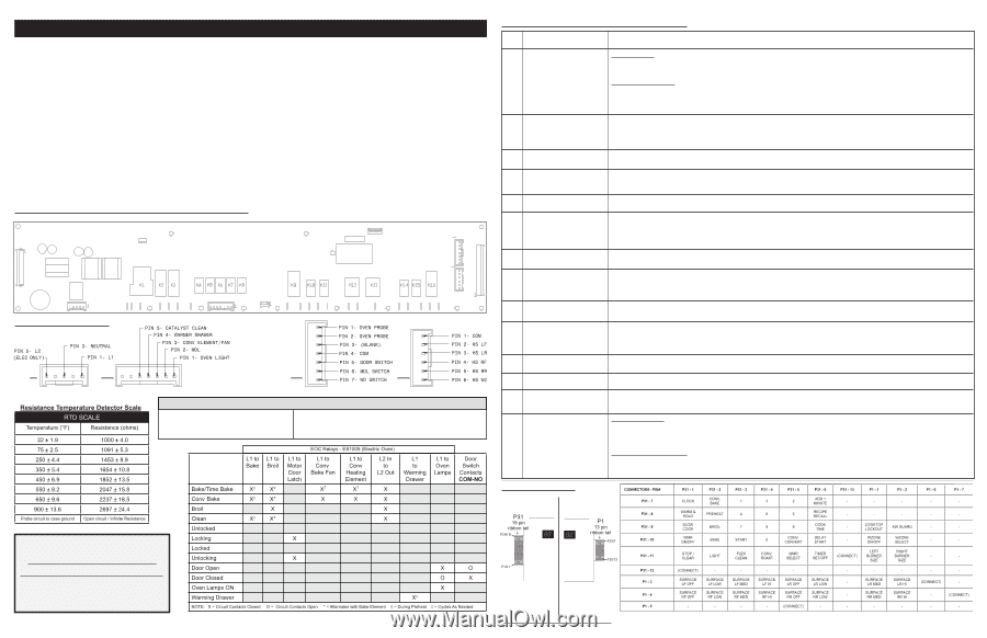
SERVICE DATA SHEET - Electric Range with ES 1000 Electronic Oven Control NOTICE - This service data sheet is intended for use by persons having electrical and mechanical training and a level of knowledge of these subjects generally considered acceptable in the appliance repair trade. The manufacturer cannot be responsible, nor assume any liability for injury or damage of any kind arising from the use of this data sheet. Safe servicing practices To avoid the possibility of personal injury and/or property damage, it is important that safe servicing practices be observed. The following are examples, but without limitation, of such practices. 1. Before servicing or moving an appliance remove power cord from electrical outlet, trip circuit breaker to OFF, or remove fuse. 2. Never interfere with the proper installation of any safety device. 3. GROUNDING: The standard color coding for safety ground wires is GREEN or GREEN WITH YELLOW STRIPES. Ground leads are not to be used as current carrying conductors. It is extremely important that the service technician reestablish all safety grounds prior to completion of service. Failure to do so will create a potential safety hazard. 4. Prior to returning the product to service, ensure that: • All electric connections are correct and secure. • All electrical leads are properly dressed and secured away from sharp edges, hightemperature components, and moving parts. • All uninsulated electrical terminals, connectors, heaters, etc. are adequately spaced away from all metal parts and panels. • All safety grounds (both internal and external) are correctly and securely reassembled. Oven Calibration Set the electronic oven control for normal baking at 350°F. Obtain an average oven temperature after a minimum of 5 cycles. Press cancel keypad to end Bake mode. Temperature Adjustment 1. While in a non-cooking mode, press and hold the bake key pad for 6 seconds. 2. The current calibration offset (temperature adjustment) should appear in the temperature display. 3. Use the number key pads (0-9) to enter the desired amount of adjustment (up to 35°F). 4. Press the self clean key pad to change the sign of the adjustment to a (-) if necessary. A positive adjustment will not display a sign. 5. Once the desired adjustment (-35° to 35° F) has been entered, press the start key pad to accept the change or the cancel key pad to reject the change. NOTE: Changing calibration affects all Baking modes. The adjustments made will not change the self-cleaning temperature. Electronic oven control (EOC) & jumper connection locations P1 P3 P4 P5 P6 P7 P8 P9 P10 P2 EOC jumper connections P31 P29 P30 P12 P13 P14 P16 P18 P19 P20 P23 P24 P25 P26 P27 P28 P2 P10 P29 P30 Tech Sheet Abbreviations and Terminology EOC = Electronic Oven Control RTD = Resistance Temperature Device. (Temp Probe or VSC = Variable Speed Control Temp Sensor) PS = Power Supply board (PS1 , PS2, etc.) TCO = Thermal Cut Out also "Thermo Disc" or "Thermal Limiter" Electronic Oven Control Fault Code Descriptions Fault Likely failure Code condition/cause F10 Runaway temperature. Oven heats when no cook cycle is programmed. Suggested Corrective Action If Oven is cold: 1. If fault code is present with cold oven test oven temperature sensor probe circuit resistance. Use RTD scale found in the tech sheet. 2. Replace probe or repair wiring connections if defective. 3. If temperature sensor probe circuit is good but fault code remains when oven is cold replace the EOC. If Oven is overheating: 1. If oven is severely overheating/heating when no cook cycle is programmed test oven temperature sensor probe circuit resistance using the RED scale found in the service tech sheet. Also verify that the temperature sensor probe in properly installed in the oven cavity. 2. Disconnect power from the range, wait 30 seconds and reapply power. If oven continues to heat when the power is reapplied, replace the EOC. NOTE: Severe overheating may require the entire oven to be replaced should damage be extensive. F11 Shorted keypad or selector 1. Reset power supply to range - Disconnect power, wait 30 seconds and reapply power. switch. 2. Check/reseat ribbon harness connections between touch panel and EOC. 3. Test keyboard circuits using test matrix. Replace touch panel if defective. 4. If keyboard ciruits check good replace the EOC. F12 EOC Internal software error Disconnect power, wait 30 seconds and reapply power. If fault returns upon power-up, replace EOC. F13 or failure. F14 Keyboard tail failure. 1. Check/reseat ribbon harness connections between keyboard touch panel and EOC.. 2. Test keyboard circuits using test matrix (below). Replace touch panel if defective. 3. If keyboard circits check good replace EOC. F15 EOC Internal hardware error Disconnect power, wait 30 seconds and reapply power. If fault returns upon power-up, replace EOC. F19 of failure. F30 Open oven sensor probe 1. (F30) Check resistance at room temperature & compare to RTD Sensor resistance chart. If resistance is correct replace the EOC. If circuit. resistance does not match the RTD chart replace RTD Sensor Probe. Check Sensor wiring harness between EOC & Sensor Probe connector. F31 Shorted oven sensor probe 2. (F31) Check resistance at room temperature, if less than 500 ohms, replace RTD Sensor Probe. Check for shorted Sensor Probe circuit. harness between EOC & Probe connector. If resistance is correct replace the EOC. F42 EOC internal software configuration error. Usually this failure code would only appear if the EOC has been replaced with an incorrect version. Verify that the correct replacement part number is being used. F60 EOC oven temperature. 1. Verify proper assembly of backguard panel. Check for damaged or loose panels, brackets, endcaps, etc. Higher than normal 2. Check for blocked ventilation slots in control panel rear cover. temperature detected on the 3. Inspect oven vent for proper assembly and air flow. EOC board. 4. Verify operation of cooling fan (if present). F62 Internal signal voltage error. Disconnect power, wait 30 seconds and reapply power. If fault returns upon power-up, replace EOC. F63 Display communication error. F64 Time Base failure - The EOC Confirm that range is connected to proper power source (50Hz or 60Hz). Generators or other portable power supplies and solar grids, etc. cannot determine if may not provide proper power supply. If power source is correct replace the EOC. connected to 50 or 60Hz power supply. F65 Keyboard short circuit or internal EOC failure. 1. Test keyboard circuits using test matrix. Replace touch panel if defective. 2. If keyboard circuits check good replace the EOC F66 EOC internal power supply failure. Disconnect power, wait 30 seconds and reapply power. If fault returns upon power-up, replace EOC. F68 High voltage condition. L1 or 1. Verify proper incoming line voltage and polarity of L1, L2 and Neutral power supply connections at range terminal block. F69 L2 may be crossed with 2. If power supply voltage and polarity are correct replace EOC. Neutral on incoming PS. F90 Door lock motor or latch F91 circuit failure. F92 F93 F94 F95 If lock motor runs: 1. Test continuity of wiring between EOC and lock switch on lock motor assy. Repair if needed. 2. Advance motor until cam depresses the plunger on lock motor switch. Test continuity of switch contacts. If switch is open replace lock motor assemblyy. 3. If motor runs and switch contacts and wiring harness test good, replace the EOC. If lock motor does not run: 1. Test continuity of lock motor windings. Replace lock motor assembly if windings are open. 2. Test lock motor operation by using a test cord to apply voltage. If motor does not operate replace lock motor assy. 3. If motor runs with test cord check continuity of wire harness to lock motor terminals. If harness is good replace the EOC. Keypad Test Matrix IMPORTANT DO NOT REMOVE THIS BAG OR DESTROY THE CONTENTS WIRING DIAGRAMS AND SERVICE INFORMATION ENCLOSED REPLACE CONTENTS IN BAG p/n 316904402en (0905) Left side Right side View: control membrane overlay from front To test keypad function check for continuity between indicated pin locations while pressing keypad. Example: To test the Bake keypad use pin #2 & pin #10 on connector P31. To test cooktop keypad use pin 1 on connector P1 & pin 9 on connector P31.
-
 1
1 -
 2
2
 |
 |