Frigidaire FGHD2433KF Wiring Diagram (All Languages) - Page 1
Frigidaire FGHD2433KF - Gallery Series - Fully Integrated Dishwasher Manual
 |
UPC - 012505111518
View all Frigidaire FGHD2433KF manuals
Add to My Manuals
Save this manual to your list of manuals |
Page 1 highlights
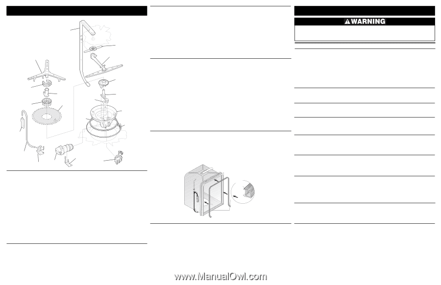
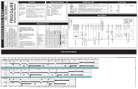
Exploded View of Wash System Delivery Tube TUB Standard Dry Air Flow When the control advances to the "dry" portion of the cycle, a vent actuation solenoid is closed. This opens the vent valve and starts the vent fan both located in the top right rear corner of the tub. The fan draws in the air from outside the tub, forcing the hot, humid air down and out the bottom of the outer door panel. This outside, cooler, dryer air helps to speed evaporation of water from the hot dishes. At the same time the heating element is continually cycled on and off. On some models the dry portion of the cycle can be extended to improve drying performance. Trouble Shooting Tips Personal Injury Hazard Always disconnect the dishwasher from the electrical power source before adjusting or replacing components. Lower Spray Arm Glass Trap Soil Filter 3rd Level Spray Arm Assy. Middle Spray Arm Assy. Spray Arm Support Filter Check Ball Sump Gasket Soil Director Volute Cover Sump Housing Heating Element Detergent and Rinse Aid Dispenser The detergent and rinse aid dispenser is a one piece component consisting of a molded detergent cup and a built-in rinse aid dispenser. The detergent cup has a spring loaded cover and the rinse aid dispenser has a removable cover. Liquid rinse aid is added to the dispenser up to the fill line indicator. The amount of rinse aid released can be adjusted by turning the arrow indicator from one, being the least amount, to four, being the greatest amount. To replace dispenser: • shut off electricity to dishwasher, • remove outer door panel assembly, • disconnect wiring to the actuator, • remove the six screws, • remove the dispenser, • replace and reinstall screws, • rewire actuator. Symptom Dishwasher will not operate when turned on. Motor hums but will not start or run. Motor trips out on internal thermal overload protector. Dishwasher runs but will not heat. Water Bottle TUB Water Inlet Tube Water Valve Circulation Motor Motor Bracket Drain Pump Pump Assembly The pump assembly is driven by a synchronous motor. Rotation is in the counterclockwise direction at 3600 RPM. The motor drives a pump which supplies 100 percent filtered water at a rate of approximately 12 GPM to one spray arm at a time. The spray arm's operation is alternated by small "pauses" of the motor during the wash cycle. Draining is accomplished by using a small separate synchronous drain pump mounted to the side of the sump. The drain pump is connected to the main pump by a small rubber hose. The drain check valve is located at the discharge end of the drain pump. The drain hose is attached by a worm gear clamp to the discharge end of the drain pump. The drain hose must have a loop at a minimum height of 32 inches in order to insure proper drainage. The main pump can easily be removed by disconnecting the upper spray arm supply tube hose, the drain pump connector hose, the wiring harness connections made at the circulation motor, the water heat thermistor located on the bottom of the pump and rotating the four sump retainers toward the middle of the sump. Tub and Door Seal The door seal is pressed into the tub channel for an interference fit. To install the seal, locate the center mark on the seal back and press into place. Next, install the bottom of the seal by creating a short turn at the bottom of the tub channel and ensuring the seal extends to the Product Specifications Electrical Rating 120 Volts, 60Hz Separate Circuit..15 amp min.- 20 amp max. Motor (Amps 1.8 Heater Wattage 900 Total Amps (load rated 10.0 TempAssure 140°F ±5°F (60°C±3°C) [with outer door in place] TempBoost 145°F ±5°F (63°C ±3°C) Heated Wash/Heated Rinse Sanitize 150°F ±5°F (66°C ±3°C) Hi-Limit Thermostat 200°F (93°C) locator ridge at the bottom of the tub. Then align and gently press the seal into the channel in only a few spots. Next, close and latch the door to allow the gasket to seat properly into the channel. Gasket Cross Section Mounting Rib Tub Interior Short Turn Water Supply Suggested minimum incoming water temperature 120°F (49°C) Pressure (PSI) min./max 20/120 Connection (NPT 3/8" Consumption (Normal Cycle 4.9 - 9.7 U.S. gal., 18.5 - 36.7 liters Water valve flow rate (U.S. GPM 83 Water recirculation rate (U.S. GPM approx. 12 Water fill time 87 sec. Detergent cover will not latch or open. Dishwasher will not pump out. Dishwasher will not fill with water. Dishwasher water siphons out. Detergent left in dispenser. Check the Following 1. Fuse (blown or tripped). 2. 120 VAC supply wiring connection faulty. 3. Electronic control board defective. 4. No 12 VAC power to control. 5. Motor (inoperative). 6. Door switch (open contacts). 7. Door latch not making contact with door switch. 8. Touch pad circuit defective. 9. No indicator lamps illuminate when START or OPTIONS are pressed. 1. Motor (bad bearings). 2. Motor stuck due to prolonged non-use. 1. Improper voltage. 2. Motor windings shorted. 3. Glass or foreign items in pump. 1. Heater element (open). 2. Electronic control board defective. 3. Wiring or terminal defective. 4. Hi-Limit thermostat defective. 1. Latch mechanism defective. 2. Electronic control board defective. 3. Wiring or terminal defective. 4. Broken spring(s). 5. Defective actuator. 1. Drain restricted. 2. Electronic control board defective. 3. Defective drain pump. 4. Blocked impeller. 5. Open windings. 6. Wiring or terminal defective. 1. Water supply turned off. 2. Defective water inlet fill valve. 3. Check fill valve screen for obstructions. 4. Defective float switch. 5. Electronic control board defective. 6. Wiring or terminal defective. 7. Float stuck in "UP" position. 1. Drain hose (high) loop too low. 2. Drain line connected to a floor drain not vented. 1. Detergent allowed to stand too long in dispenser. 2. Dispenser wet when detergent was added. 3. Detergent cover held closed or blocked by large dishes. 4. Improper incoming water temperature to properly dissolve detergent. 5. See "Detergent cover will not open." Remedy 1. Replace fuse or reset breaker. 2. Repair or replace wire fasteners at dishwasher junction box. 3. Replace control board. 4. Replace control board. 5. Replace motor/impeller assembly. 6. Replace latch assembly. 7. Replace latch assembly. 8. Replace console assembly. 9. Replace console assembly. 1. Replace motor assembly. 2. Rotate motor impeller. 1. Check voltage. 2. Replace motor/impeller assembly. 3. Clean and clear blockage. 1. Replace heater element. 2. Replace control board. 3. Repair or replace. 4. Replace thermostat. 1. Replace dispenser. 2. Replace control board. 3. Repair or replace. 4. Replace dispenser. 5. Replace dispenser. 1. Clear restrictions. 2. Replace control board. 3. Replace pump. 4. Check for blockage, clear. 5. Replace pump assembly. 6. Repair or replace. 1. Turn water supply on. 2. Replace water inlet fill valve. 3. Disassemble and clean screen. 4. Repair or replace. 5. Replace control board. 6. Repair or replace. 7. Clean float. 1. Repair to proper 32-inch minimum height. 2. Install air gap at counter top. 1. Instruct customer/user. 2. Instruct customer/user. 3. Instruct customer/user on proper loading of dishes. 4. Incoming water temperature of 120°F is required to properly dissolve dishwashing detergents. 020905
-
 1
1 -
 2
2
 |
 |