Frigidaire FGIF3061NF Service Data Sheet - Page 4
Electronic Surface Element Control System ESEC Error Code Descriptions - lowes
 |
View all Frigidaire FGIF3061NF manuals
Add to My Manuals
Save this manual to your list of manuals |
Page 4 highlights
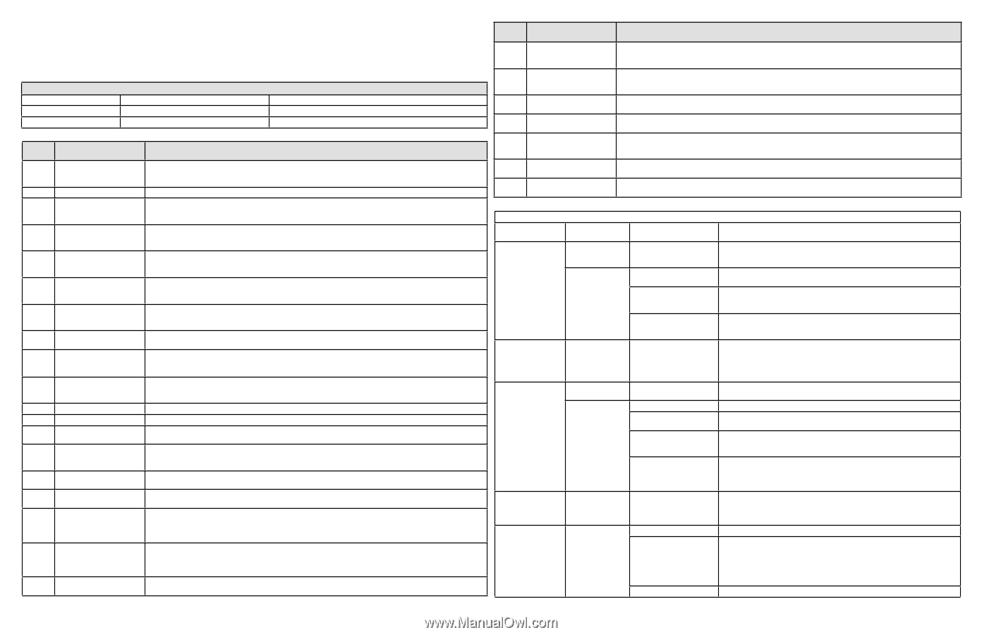
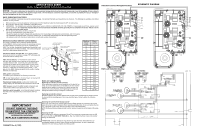
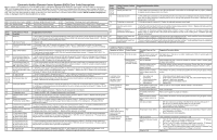
Electronic Surface Element Control System (ESEC) Error Code Descriptions When a specific error condition occurs in the ESEC system a code will be displayed in the electronic control panel. The error codes are displayed as "EO" in the left display followed by the code number in the right display. For each Error Code there is a listing of the likely cause or failure condition, as well as suggested corrective actions to be taken. Always reset the power by disconnecting or turning off the power supply for 30 seconds to see if the failure condition will clear. If the error code returns perform the steps one at a time in the order listed below to correct the specific failure condition. NOTE: If multiple changing error codes are displayed check for disconnected wires or cables. EOC = Electronic Oven Control UIB = User Interface Board VSC = Variable Speed Control Tech Sheet Abbreviations and Terminology ESEC = Electronic Surface Element Control TST = Touch Sensor Technology (touch control glass panel) TSEC = Touch Sensor Electronic Control RTD = Resistance Temperature Device. (Temp Probe or Temp Sensor) PS = Power Supply board (PS1 , PS2, etc.) TCO = Thermal Cut Out also "Thermo Disc" or "Thermal Limiter" Error Code 11 13 14 15 20/27 21/28 23 30, 35 31, 32, 34, 36, 37, 40 33 38 39 41 42, 43 44 45 51 52 55 56 63 64 67 68 70 75 Likely Cause or Failure Condition Suggested Corrective Action Stuck key 1. Verify nothing is touching the potentiometer/display boards. Disconnect Power, wait 30 seconds and repower. If fault returns: 2.Check/reseat connectors and harnesses between ESEC-UIB and potentiometer/display boards; 3. Replace ESEC-UIB; 4. Replace potentiometer/display boards. UIB Internal Failure 1. Replace UIB. Potentiometer/display boards 1. Disconnect Power, wait 30 seconds and repower. If fault returns: 2.Check/reseat connectors and harnesses connector between ESEC-UIB and the potentiometer/display boards; 3. Replace ESEC-UIB; 4. Replace potentiometer/display boards. ESEC self-test failure 1. Verify cables and connections on the ESEC UIB are not damaged and are properly installed. If fault returns: 2.Check/reseat harnesses between ESEC-UIB and the potentiometer/display boards; 3. Replace ESEC-UIB; 4. Replace ESEC power supply board. Communication failure between generator board and UIB - left cooking zones 1. Verify communication harness between left and right side generator circuit board is not damaged and is properly installed; 2. Verify AC power harness is not damaged and is properly installed; 3. Verify ID1 jumper is properly installed; 4. Replace the UIB; 5. Replace the left side generator board. Communication failure between generator board and UIB - right cooking zones 1. Verify communication harness between left and right side generator circuit board is not damaged and is properly installed; 2. Verify AC power harness is not damaged and is properly installed; 3. Verify ID1 jumper is properly installed; 4. Replace the UIB; 5. Replace the right side generator board. Communication failure be- 1. Verify AC power supply to the appliance is 240V; 2. Verify communication harness between the ESEC UIB and the tween both generator boards left side generator board is not damaged and is properly installed; 3. Replace the UIB; 4. Replace both communication and UIB harnesses; 5. Replace the left side generator board. AC input too high AC input too low 1. Verify AC power supply to the appliance is 240V; 2. Verify cables and connections on the left side generator circuit board are not damaged and are properly installed; 3. Replace the left side generator circuit board. Internal generator error 1. Verify cables and connections on the left side of the generator circuit board are not damaged and are properly installed; 2. Replace the left side generator circuit board. Cooling fan blocked Cooling fan not connected Configuration error Induction sensor (coils) defect General pot detection Pot detection sensor failure Generator circuit board temperature warning Generator circuit board temperature alarm LF temp sensor failure LR temp sensor failure RF temp sensor failure RR temp sensor failure LF temp sensor too hot LR temp sensor too hot RF temp sensor too hot RR temp sensor too hot AC input too high AC input too low 1. Verify cables and connections on the left side generator circuit board are not damaged and are properly installed; 2. Verify there is nothing touching or interfering with the fan on the left side generator circuit board; 3. Replace the left side generator circuit board. 1. Verify fan is properly connected; 2. Replace the left side generator circuit board. 1. Replace the ESEC UIB; 2. Replace both generator circuit boards. 1. Verify if the left side inductor (coils) are connected properly (measure approx. 0 Ohm); 2. Replace left side generator circuit board if 0 Ohm, otherwise replace the inductor (coil). 1. Verify pans are the proper material (magnet sticks to bottom of pan); 2. Verify pan is in the proper condition (not warped, rusty); 3. Verify the pan is the proper size and placed correctly on the cooking zone. 4. Replace left side generator circuit board. 1. Ensure cooktop is not being used with a dry pan at a high temperature setting; 2. Verify that installation follows the installation instructions, check ventilation; 3. Allow zone to cool before continuing to cook. 1. Ensure cooktop is not being used with a dry pan at a high temperature setting; 2. Verify that installation follows the installation instructions, check ventilation; 3. Replace left side generator circuit board. 1. Verify induction temperature sensor is properly connected (see wiring diagram); 2. Verify the inductor temperature sensor is properly installed and not damaged (measure approx. 100K Ohm at room temperature); 3. Replace applicable generator circuit board, left or right (see wiring diagram). 1. Ensure cooktop is not being used with a dry pan at a high temperature setting; 2. Verify the inductor temperature sensor is properly installed and not damaged (measure approx. 100K Ohm at room temperature); 3. Replace applicable generator circuit board, left or right (see wiring diagram). 1. Verify AC power supply to the appliance is 240V; 2. Verify cables and connections on right side generator circuit board are not damaged and are properly installed; 3. Replace the right side generator circuit board. Error Code 71, 72, 74, 76, 77, 80 73 78 Likely Cause or Failure Condition Internal generator error Suggested Corrective Action 1. Verify cables and connections on the right side generator circuit board are not damaged and are properly installed; 2. Replace the right side generator circuit board. Cooling fan blocked Cooling fan not connected 1. Verify cables and connections on the right side generator circuit board are not damaged and are properly installed; 2. Verify there is nothing touching or interfering with the fan on the right side generator circuit board; 3. Replace the right side generator circuit board. 1. Verify fan is properly connected; 2. Replace the right side generator circuit board. 81 Induction sensor (coils) defect 1. Verify if the right side inductor (coils) are connected properly (measure approx. 0 Ohm); 2. Replace right side generator circuit board if 0 Ohm, otherwise replace the inductor (coil). 82 General pot detection 1. Verify pans are the proper material (magnet sticks to bottom of pan); 2. Verify pan is in the proper condition (not 83 Pot detection sensor failure warped, rusty); 3. Verify the pan is the proper size and placed correctly on the cooking zone. 4. Replace right side generator circuit board. 84 Generator circuit board tem- 1. Ensure cooktop is not being used with a dry pan at a high temperature setting; 2. Verify installation follows the installation perature warning instructions, check ventilation; 3. Allow zone to cool before continuing to cook. 85 Generator circuit board tem- 1. Ensure cooktop is not being used with a dry pan at a high temperature setting; 2. Verify installation follows the installation perature alarm instructions, check ventilation; 3. Replace right side generator circuit board. Additional Failure Conditions Symptom or Failure Control Display Pan does not heat up. Normal operation Flashing power level Display and pan does not heat. Individual knobs/ controls cannot be used or cannot always be used. Cooking power too low or shuts down prematurely. None None Normal Operation Steady "HE" in display when cooking zone is cold and switched off. Cooktop does not initialize/operate. "HE" Blank No display No beep Possible Cause or Condition Pan too small for proper pan detection and only works with low power. Pan not detected. Induction surface unit not correctly connected or surface unit open. Distance between surface unit and glass ceramic too large. 1. Test cables and connections. 2. Potentiometer/display boards defective. 3. UIB defective. Fluids spilled or object lying on control panel keypads. Ventilation slots obstructed. Unsuitable pots (bottom bent). Distance between surface unit and glass ceramic too large. Fan does not start. Temperature sensor defect. Suggested Corrective Action Use larger pan or this pan on a smaller cooking zone. Refer to owners guide for proper pan selection. Check whether the pots or pans are suitable for induction. Refer to owners guide for proper pan selection. Check the surface unit wire terminal connections. Ensure that they are properly connected and tightened. Test continuity of element (should be less than 1 ohm). Check whether the surface unit is properly positioned and touching the glass cooktop surface. 1. Follow instructions for proper use of controls. 2. Verify harness connections between UIB, and potentiometer/display boards. Replace if defective or damaged. 3. Replace potentiometer/display boards 4. Replace UIB. Clean up spills or remove objects. Restart cooktop in normal manner. Clear vent openings. Follow owner's guide for proper pan selection. Check whether the surface unit is properly positioned and touching the glass cooktop surface. 1. With two cook zones operating, verify that the fan runs at a slow speed. If fans do not run, check for foreign objects or stuck fan motor. 2. Test continuity of motor windings. Replace motor if open. 3. Replace induction control assembly. 1. Test surface unit RTD approx. 1K ohms at room temperature. Replace surface unit if resistance is not correct. 2. Replace induction control assembly. UIB not powered. Defective UIB power supply (PS2). Defective UIB. Verify installation and harness connections to UIB. 1. Check for 120 volts AC at the power supply board connector P1 between pins 1 and 4. Test harness if voltage is not present. 2. Test for 8 volts DC output at the power supply board connector P3 between Pins 1 and 2. Replace power supply board if voltage is not correct. 3. Test for 16 volts DC at output at power supply board connector P3 between Pins 1 and 3. Replace power supply board if voltage is not correct. Replace UIB.
-
 1
1 -
 2
2 -
 3
3 -
 4
4
 |
 |