Frigidaire FPHD2491KF Installation Instructions (English) - Page 2
Water Line, Electrical Supply - dishwasher
 |
UPC - 012505111433
View all Frigidaire FPHD2491KF manuals
Add to My Manuals
Save this manual to your list of manuals |
Page 2 highlights
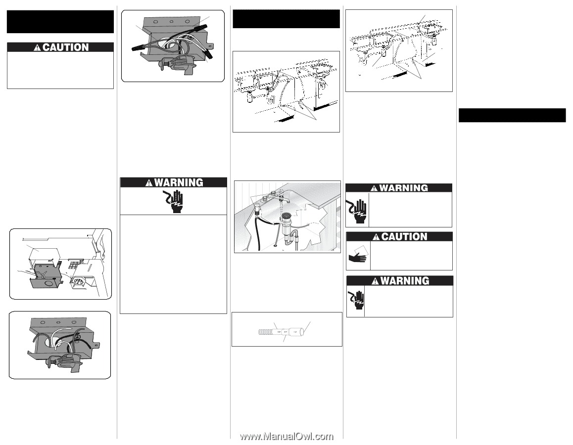
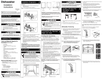
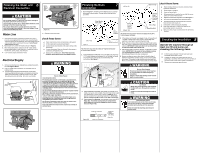
Finishing the Water and 6 Electrical Connection GREEN WIRE TO GREEN WIRE (GROUND) BLACK WIRE TO BLACK WIRE (HOT) Property Damage Do not solder within 6" of the water inlet valve. Damage to the plastic parts in the valve may occur. Use care that no sealer, dirt, or other objects enter the valve. Damage to the filter screen may occur. Be sure the dishwasher is placed where the water inlet valve will be kept from freezing. If the valve freezes, it may rupture and flooding may occur. Figures 6a WHITE WIRE TO WHITE WIRE (NEUTRAL) Water Line 4. Replace junction box cover. 1. Flush water line before connecting it to water inlet valve to prevent early clogging of filter screen. Place a bunched towel over end of line to prevent splashing. Open water supply valve for a few seconds and let water drain into a pan. Turn off water supply at shut-off valve. 2. Route water line to water inlet valve as shown in Figure 4. 3. While firmly pulling water supply line into 90° elbow, tightly connect water supply to water inlet valve. Supply line must be free of kinks, scales, chips, and lubricants. 4. Turn on water supply and check for leaks. check these items: ‰ Water and electrical lines are hooked up to dishwasher. ‰ All four leg levelers are positioned properly. ‰ Cabinet Seals are positioned on the sides and top of the dishwasher. ‰ Cabinet Attachment Clips are attached to the cabinet or countertop and kickplate brace. ‰ Replace Toe and Kickplate. Note: When replacing Kickplate and kickplate brace hand tighten screws. Electrical Supply 1. Remove junction box cover and pull house wiring into junction box. See Figures Below. 2. Use a UL listed conduit connector (not included) at box to stabilize wiring. 3. Connect incoming black lead to dishwasher's black lead, incoming white lead to dishwasher's white lead and incoming green lead to dishwasher's green lead with wire nuts. (See Grounding Instruction Warning). Wire nuts must be tight. JUNCTION BOX COVER Electric Shock Hazard Grounding Instructions: The dishwasher must be connected to a grounded metal, permanent wiring system or an equipment-grounding conductor must be run with the circuit conductors and connected to the appliance's equipment grounding terminal or lead. It is the consumer's responsibility to contact a qualified installer to make sure the electrical installation conforms with the National Electrical Code and local codes and ordinances. Do not connect the dishwasher to the power supply until the appliance is permanently grounded. All wiring connections must be enclosed in the junction box. This unit has copper lead wires. Joining aluminum building wire to stranded copper wire should be done by a qualified electrician using materials recognized by UL and local codes. Do not use an extension cord. Such use can result in fire, electrical shock, or other personal injury. Failure to follow these instructions could result in death or serious injury. Finishing the Drain 7 Connection 1. Review Figures 7, 8 and 9 to see the different ways to connect dishwasher to drain system. Choose method that best suits your need. Entry Must be Above Trap "Y" Branch Tailpiece Sink at Left Drain Air Gap Remove Knockout Plug in Disposer Figure 9(b) Alternate Drain Through Floor into Separate Trap Sink at Right 2" Drain Hose Hole The drain hose loop must be at least 32" high from the floor to insure proper drainage. check these items: ‰ Water and drain lines have no kinks and move freely behind the dishwasher. ‰ Water supply is turned on. ‰ Joints are free of leaks. ‰ Wiring connections to junction box are tight all access panels are secured back in place. ‰ Replace kickplate and kickplate brace. (See Figure 1) ‰ Drain hose is assembled to Drain Hose Connector. ‰ All packing materials and consumer literature have been removed from inside unit. ‰ Dishwasher is level and securely fastened. ‰ Open and close door to make sure it does not hit surrounding cabinet or countertop. ‰ Make sure that all tape is removed from the Silverware Baskets. Sink at Left Figure 7 Sink at Right 2" Drain Hose Hole The drain hose loop must be at least 32" high from the floor to insure proper drainage. 2. If you connect to a sink drain, entry will need to be above trap. A "Y" branch tailpiece and connector kit, not included, will make this method easier and includes all needed fittings and instructions. See Figure 7. 5. If the cabinet wall is wood, sand edges of hole until smooth and rounded. If cabinet wall is metal, cover all sharp edges with electrical or duct tape to avoid cutting drain hose. 6. Move unit back in place while routing drain hose through access hole. Use caution to prevent damage to the dishwasher, floor and cabinets. IMPORTANT: Make sure there are no sharp bends or kinks that might restrict drain flow. 7. Secure drain hose to sink drain, disposer, or separate trap with a clamp. IMPORTANT: Be careful not to overtighten clamp or you may damage end of hose. Do not connect hose to horizontal pipe between sink drain and disposer. 8. Be sure unit does not rest on drain hose. It should be free of electrical components and door springs. Do not cut corrugated drain hose. Pull excess through cabinet and place under sink. Make sure hose does not come in contact with any sharp edges. 8 Checking the Installation Operate the machine through at least one fill and pump-out, checking the following items: ‰ At first fill, approximately 1 minute make sure water completely covers filter surface. ‰ At pump-out: (pump-out is either when the cycle is completed or canceled. refer to the Use and Care Manual for Start/Cancel), make sure all water is pumped out. ‰ Check water connections again for leaks. Air Gap 7 Right Side Installation Electric Shock Hazard Disconnect electrical power at the fuse box or circuit breaker box before beginning installation. Failure to follow this warning could result in death or serious injury. Figure 8 3. If you connect to a sink trap, local codes may require you to install an air gap kit, (not included). The drain hose will be routed from dishwasher to air gap inlet as shown in Figure 8. An air gap kit is available from a plumbing supply store. (If the drain hose is installed through the floor, an air gap is necessary). 4. If you connect to a disposer, the large end of drain hose will fit. Figure 9(a). The knock out plug must be removed from inside disposer inlet before making the final fit to drain hose. See Figure 9(b). Cut for 5/8" connection. Figure 9(a) Cut for 3/4" connection. Larger end of hose fits disposer inlet fitting. Drain Hose Cut Hazard Metal color panels are sharp and should be handled with care. Wear gloves to protect hands. Failure to follow this warning may result in injury. Electric Shock Hazard If all connections are correct, there are no leaks, and unit runs properly, replace the kickplate assembly before placing unit into operation. Failure to follow this warning could result in electric shock.
-
 1
1 -
 2
2
 |
 |