Frigidaire GLTF2940FB Installation Instructions - Page 4
Location Of Your Washer, Unpacking
 |
View all Frigidaire GLTF2940FB manuals
Add to My Manuals
Save this manual to your list of manuals |
Page 4 highlights
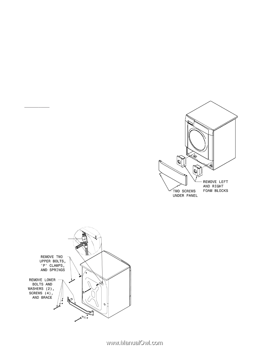
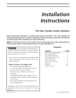
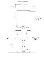
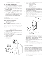
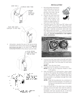
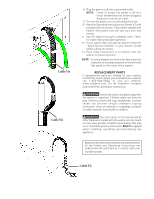
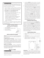
LOCATION OF YOUR WASHER DO NOT INSTALL YOUR WASHER: 1. In an area exposed to dripping water or outside weather conditions. The ambient temperature should never be below 60 ° F (15.6 ° C) for proper washer (detergent breakdown) operation. 2. In an area where it will come in contact with curtains or drapes. 3. In an area (garage or garage-type building) where gasoline of other flammables are kept or stored (including automobiles). 4. On carpet. Floor MUST be solid with a maximum slope of 1/2 in. per foot (1.27 cm per 30.5 cm). To ensure vibration or movement does not occur, reinforcement of the floor may be necessary. IMPORTANT MINIMUM INSTALLATION CLEARANCES When installed in alcove or closet: Sides, Rear = 0 in. (0 cm) Top = 0 in. (0 cm) When installed in closet: Front = 1 in. (2.54 cm) Closet door ventilation required: 2 louvered openings each 60 in2 (387 cm2), 3 in. (7.6 cm) from top and bottom of door. 6. Remove the following from the back panel of the washer: 4 packaging bolts, 2 packaging springs, 2 washers, 2 metal "P" clamps, 4 screws, 1 packaging brace. 7. Remove the 4 transport plugs from the literature pack and install them in the corresponding holes in the back panel of the washer. 8. Remove the 4 small hole plugs from the literature pack and install them in the side panel holes vacated by the packaging brace. 9. Using the shipping posts, prop up the front of the washer approximatley 2 inches to gain access to the service panel screws. 10. Remove the 2 screws and remove the service panel. UNPACKING 1. Cut the shipping carton along the dotted line along the base of the unit. 2. While in the carton carefully lay the washer on its back side. 3. Remove the styrofoam base. 4. Carefully return the washer to an upright position and remove the carton. 5. Carefully move the washer to within 4 feet (122cm) of the final location. POWER CORD 11. Remove the the two (2) styrofoam blocks located under the drum (a yellow ribbon surrounds the items to be removed). Lift up on the drum, tilt the base of the foam blocks inwards toward the rear of the washer until free, then pull them out. 12. Remove and discard the yellow ribbon from the front of the washer. 13. Replace the service panel and screws. NOTE: If the washer is to be transported at a later date, the shipping support hardware must be reinstalled to prevent shipping damage. Drain Hose Installation The drain hose is field installed to allow hose orientation to the left or right, up or down depending on location of the house drain. The hose is shipped in the washer tub with the spring clamp on the coupler elbow and drain hose hanger installed on the end of the hose. 1. Remove the drain hose from the tub of the washer. 2. Push the hose onto the drain coupler at the upper left of the washer back panel until the hose contacts the STOP RIB. 4
-
 1
1 -
 2
2 -
 3
3 -
 4
4 -
 5
5 -
 6
6 -
 7
7 -
 8
8 -
 9
9 -
 10
10 -
11
-
12
 |
 |