Frigidaire PLCF489GC Installation Instructions - Page 5
Junction Box Location, Range Placement - dimensions
 |
UPC - 057112083445
View all Frigidaire PLCF489GC manuals
Add to My Manuals
Save this manual to your list of manuals |
Page 5 highlights
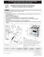
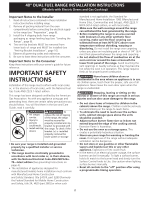
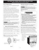
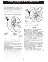
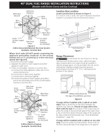
40" DUAL FUEL RANGE INSTALLATION INSTRUCTIONS (Models with Electric Ovens and Gas Cooktop) Junction Box Location Locate junction box as shown in Figure 7. If a service cord is used, the wall receptacle should be located in accordance with the dimensions below. Figure 5 3-Wire (Grounded Neutral) Electrical System (example: Junction Box) Where local codes DO NOT permit connecting the appliance grounding conductor to the neutral (white) wire or if connecting to 4-wire electrical system (see Figure 6). 1. Disconnect the power supply. 2. Separate the green (or bare copper) and white appliance cable wires. 3. In the circuit breaker, fuse box or junction box: a) Connect the white appliance cable wire to the neutral (white) wire. b) Connect the 2 black wires together. c) Connect the 2 red wires together. d) Connect the green (or bare copper) grounding wire to the grounding wire of the circuit breaker, fuse box or junction box. 10" (25.4 cm) 7" Max. (17.8 cm Max.) Center Line of Range 20" (50.8 cm) 10" (25.4 cm) WALL FLOOR Locate Electrical Hook-up Inside Shaded Area Figure 7 Center Line of Range Range Placement To eliminate the risk of burns or fire by reaching over heated surface units, cabinet storage space located above the range should be avoided. If cabinet storage space is to be provided, the risk can be reduced by installing a range hood that projects horizontally a minimum of 5" (12.7 cm) beyond the bottom of the cabinet. Center Line of Range Figure 6 4-Wire Electrical System (example: Junction Box) Follow instructions for the type of installation you have Figure 8 If range will be installed with a cabinet on both sides, draw a center line on the floor between the cabinets (see figure 8). If back of range will not be flush with the wall (the location of the outlet may not allow the range to be positioned against the wall), draw a line on the floor where the back edge of the range will be. Now install anti-tip brackets (see "Anti-tip Brackets Installation", page 10). If range will be installed with a cabinet on one side only, move the range into final position. Draw a line on the floor along the side of the range that is not against 5
-
 1
1 -
 2
2 -
 3
3 -
 4
4 -
 5
5 -
 6
6 -
 7
7 -
 8
8 -
 9
9 -
 10
10 -
 11
11 -
12
-
13
-
14
-
15
-
16
-
17
-
18
-
19
-
20
-
21
-
22
-
23
-
24
 |
 |
