Fujitsu MHT2060BH Manual/User Guide - Page 10
Connector specifications for host system
 |
UPC - 000053779588
View all Fujitsu MHT2060BH manuals
Add to My Manuals
Save this manual to your list of manuals |
Page 10 highlights
Installation Conditions 3.3.2 Signal segment and power supply segment Figure 3.9 shows each segment of the SATA interface connector and pin numbers. Power supply segment Signal segment View from the connector side P1 pins in the power S1 pins in the signal segment supply segment View from the PCA side Figure 3.9 Power supply pins (CN1) 3.3.3 Connector specifications for host system Table 3.2 lists the recommended specifications for the host interface connectors. Table 3.2 The recommended connector specifications for the host system Segment SATA interface and power supply Name Host receptacle Model (Manufacturer) 67492-0220 (Molex) or compatibles 3-10 C141-E203-02EN
-
 1
1 -
2
-
3
-
4
-
 5
5 -
 6
6 -
 7
7 -
 8
8 -
 9
9 -
 10
10 -
 11
11 -
 12
12
 |
 |

Installation Conditions
3-10
C141-E203-02EN
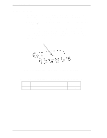
3.3.2
Signal segment and power supply segment
Figure 3.9 shows each segment of the SATA interface connector and pin
numbers.
Power supply
segment
P1 pins in the power
supply segment
S1 pins in the signal
segment
View from the
connector side
View from the
PCA side
Signal segment
Figure 3.9
Power supply pins (CN1)
3.3.3 Connector specifications for host system
Table 3.2 lists the recommended specifications for the host interface connectors.
Table 3.2
The recommended connector specifications for the host system
Segment
Name
Model (Manufacturer)
SATA interface
and power supply
Host receptacle
67492-0220 (Molex) or compatibles