Garmin Compact Reactor 40 Hydraulic Autopilot with GHC 20 and Shadow Drive Techn - Page 5
Installation Procedures
 |
View all Garmin Compact Reactor 40 Hydraulic Autopilot with GHC 20 and Shadow Drive Technology Pack manuals
Add to My Manuals
Save this manual to your list of manuals |
Page 5 highlights
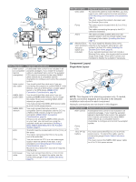
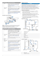
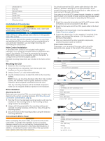
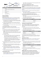
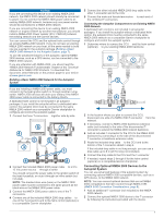
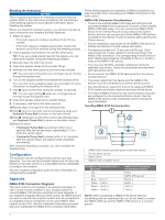
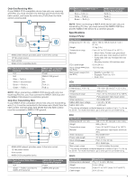
Starboard line  Port line à Shut-off valves Ä Pump Å Upper helm Æ Lower helm Ç Steering cylinder È Installation Procedures CAUTION Always wear safety goggles, ear protection, and a dust mask when drilling, cutting, or sanding. NOTICE When drilling or cutting, always check what is on the opposite side of the surface. After you have planned the autopilot installation on your boat and satisfied all of the mounting and wiring considerations for your particular installation, you can begin mounting and connecting the components. Helm Control Installation A dedicated helm control is not included in all autopilot packages. If you install the autopilot without a dedicated helm control, the autopilot CCU must be connected to the same NMEA 2000 network as a compatible Garmin chartplotter to configure and control the autopilot system. Detailed mounting instructions are included in the helm control box. Mounting the CCU 1 Determine the mounting location. 2 Using the CCU as a template, mark the two pilot hole locations on the mounting surface. 3 Using a 3 mm (1/8 in.) bit, drill the pilot holes. 4 Use the included screws to attach the CCU to the mounting surface. NOTE: If you use mounting hardware other than the provided screws, the hardware must be quality stainless or brass material to avoid magnetic interference with the CCU. Test any mounting hardware with a handheld compass to make sure no magnetic fields are present in the hardware. ECU Installation Mounting the ECU Before you can mount the ECU, you must select a location and determine the correct mounting hardware (ECU Mounting and Connection Considerations, page 2). 1 Hold the ECU in the intended mounting location and mark the locations of the mounting holes on the mounting surface, using the ECU as a template. 2 Using a drill bit appropriate for the mounting surface and selected mounting hardware, drill the four holes through the mounting surface. 3 Secure the ECU to the mounting surface using the selected mounting hardware. Connecting the ECU to Power WARNING When connecting the power cable, do not remove the in-line fuse holder. To prevent the possibility of injury or product damage caused by fire or overheating, the appropriate fuse must be in place as indicated in the product specifications. In addition, connecting the power cable without the appropriate fuse in place voids the product warranty. You should connect the ECU power cable directly to the boat battery, if possible. Although it is not recommended, if you connect the power cable to a terminal block or other source, you must connect it through a 40 A fuse. If you plan to route the ECU power through a breaker or a switch near the helm, you should consider using an appropriately sized relay and control wire instead of extending the ECU power cable. 1 Route the connector-terminated end of the ECU power cable to the ECU, but do not connect it to the ECU. 2 Route the bare-wire end of the ECU power cable to the boat battery. If the wire is not long enough, it can be extended (Power Cable Extensions, page 5). 3 Connect the black wire (-) to the negative (-) terminal of the battery, and connect the red wire (+) to the positive (+) terminal of the battery. 4 After you install all of the other autopilot components, connect the power cable to the ECU. Power Cable Extensions If necessary, you can extend the power cable using the appropriate wire gauge for the length of the extension. Item À Á  Description Fuse Battery 9 ft. (2.7 m) no extension Item Description Splice 10 AWG (5.26 mm²) extension wire Fuse 8 in. (20.3 cm) Battery 8 in. (20.3 cm) Up to 15 ft. (4.6 m) Item Description Splice 8 AWG (8.36 mm²) extension wire Fuse 8 in. (20.3 cm) Battery 8 in. (20.3 cm) Up to 23 ft. (7 m) 5
-
 1
1 -
 2
2 -
 3
3 -
 4
4 -
 5
5 -
 6
6 -
 7
7 -
 8
8 -
 9
9 -
 10
10 -
 11
11 -
12
 |
 |
