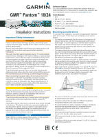
Garmin Fantom Radar Installation Instructions - Page 3
Radar Operation, Specifications - 24
 |
View all Garmin Fantom Radar manuals
Add to My Manuals
Save this manual to your list of manuals |
Page 3 highlights
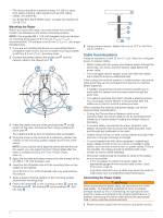
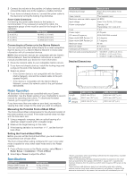
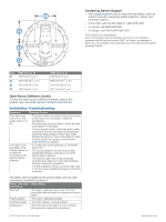
2 Connect the red wire to the positive (+) battery terminal, and connect the black wire to the negative (-) battery terminal. 3 If you have not already done so, connect the power cable to the device by turning the locking ring clockwise. Power Cable Extensions Connecting the power cable directly to the battery is recommended. If it is necessary to extend the cable, the appropriate gauge of wire must be used for the length of the extension. Distance 2 m (6.5 ft.) Wire Gauge 16 AWG (1.31 mm²) 4 m (13 ft.) 6 m (19 ft.) 14 AWG (2.08 mm²) 12 AWG (3.31 mm²) Connecting to a Device or to the Marine Network You can connect the radar either directly to a radar-compatible Garmin device or to a Garmin Marine Network to share radar information with all connected devices. NOTE: Not all Garmin devices are compatible with the Garmin Marine Network. See the installation instructions or owner's manual provided with your device for more information. 1 Route the network cable to your compatible Garmin device. 2 If you have not already done so, install the locking rings and o-rings on the end of the network cable. 3 Select an option: • If the Garmin device is not compatible with the Garmin Marine Network, connect the network cable to the port labeled RADAR. • If the device is compatible with the Garmin Marine Network, connect the network cable to the port labeled NETWORK. Radar Operation All functions of this radar are controlled with your Garmin chartplotter. See the Radar section of your chartplotter's owner's manual for operating instructions. To download the latest manual, go to support.garmin.com. If you have more than one radar on your boat, you must be viewing the radar screen for the radar you want to configure. Measuring the Potential Front-of-Boat Offset The front-of-boat offset compensates for the physical location of the radar scanner on a boat, if the radar scanner does not align with the bow-stern axis. 1 Using a magnetic compass, take an optical bearing of a stationary target located within viewable range. 2 Measure the target bearing on the radar. 3 If the bearing deviation is more than +/- 1°, set the front-of- boat offset. Setting the Front-of-Boat Offset Before you can set the front-of-boat offset, you must measure the potential front-of-boat offset. The front-of-boat offset setting configured for use in one radar mode is applied to every other radar mode and to the Radar overlay. 1 From a Radar screen or the Radar overlay, select Menu > Radar Setup > Installation > Front of Boat. 2 Select Up or Down to adjust the offset. Specifications Specification Weight GMR Fantom 18 WeightGMR Fantom 24 Measurement 6.3 kg (13.8 lb.) 7.7 kg (17 lb.) Specification Measurement Temperature range From -25 to 70°C (from -13 to 158°F) Case material Thermoplastic resin Maximum antenna rotation speed 48 RPM Input voltage From 10 to 32 Vdc, 2.5 A max. Power consumption1 Standby: 3 W Transmitting: 18.1 to 24.4 W Fuse 7.5 A Power output 40 W peak RF transmit frequency 9335-9455 MHz nominal Beam width GMR Fantom 18 5.2 degrees Beam width GMR Fantom 24 3.7 degrees Maximum range 48 nm Minimum range 6 m (20 ft.) Compass-safe distance 0.25 m (10 in.) Minimum safe operating distance2 • 100 W/m² = 0.08 m (3.15 in.) • 50 W/m² = 0.12 m (4.72 in.) • 10 W/m² = 0.26 m (10.24 in.) Detailed Dimensions Item Length (width) (height) GMR Fantom 18 508.2 mm (20 in.) 504.7 mm (19 7/8 in.) 248.3 mm (9 3/4 in.) GMR Fantom 24 645.4 mm (25 7/16 in.) 642.5 mm (25 5/16 in.) 250.3 mm (9 7/8 in.) 1 Power consumption when transmitting is affected by the range setting. A greater range setting uses more power. 2 When it is transmitting, the radar should be located in a position on the vessel that is at least this far from people. (IEC 60936-1, clause 3-27.1, specifies the maximum distances from the antenna at which radio frequency (RF) levels can be expected.) These minimum safe distances apply for a transmitting radar with a rotating antenna, and are much larger when the antenna is not rotating. If rotation of the antenna is obstructed for any reason, the transmitter will automatically turn off. 3
-
 1
1 -
 2
2 -
 3
3 -
 4
4
 |
 |
