Garmin GHP 12 Autopilot System Installation Instructions - Page 8
General Component Layout Diagram
 |
View all Garmin GHP 12 Autopilot System manuals
Add to My Manuals
Save this manual to your list of manuals |
Page 8 highlights
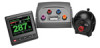
General Component Layout Diagram Refer to this diagram for component-layout reference only. Follow the detailed installation instructions for each component (pages 9-14). ➊ ➌ ➋ ➍ ➎ ➏ Item ➊ ➋ ➌ ➍ ➎ ➏ Description GHC 20 12-24 Vdc battery CCU Important Considerations In order for the autopilot to turn on, the yellow wire from the GHC 20 data cable must be connected to the yellow wire from the CCU/ECU Interconnect cable, and the black wire from the GHC 20 data cable must be connected to the same ground as the ECU (page 12). The ECU can connect to a 12-24 Vdc power source. The NMEA 2000 power cable must be connected to a 9-16 Vdc power source. The CCU must be installed in the front half of the boat, no higher than 10 ft. (3 m) above the waterline Drive unit ECU NMEA 2000 network Do not cut or extend the drive unit cables. If you are using the GHP 12 with a non-Garmin drive unit, you must purchase a GHP 12 drive unit cable (page 9). The ECU can either be connected to a 12 or a 24 Vdc battery. The GHC 20 and the CCU must be connected to the NMEA 2000 network using the included T-connectors (page 12). If there is not an existing NMEA 2000 network on your boat, you can build one using the supplied cables and connectors (page 13). 8 GHP 12 Installation Instructions
-
 1
1 -
2
-
 3
3 -
 4
4 -
 5
5 -
 6
6 -
 7
7 -
 8
8 -
 9
9 -
 10
10 -
 11
11 -
 12
12 -
 13
13 -
14
-
15
-
16
-
17
-
18
-
19
-
20
-
21
-
22
-
23
-
24
-
25
-
26
-
27
-
28
-
29
-
30
-
31
-
32
 |
 |
