Garmin GMR 604 Open Array Antenna xHD Installation Instructions - Page 3
Installing the Mounting Studs and Seals, Mounting the Radar
 |
View all Garmin GMR 604 Open Array Antenna xHD manuals
Add to My Manuals
Save this manual to your list of manuals |
Page 3 highlights
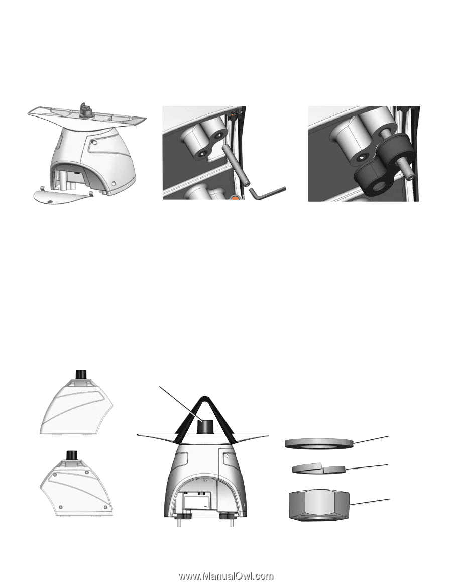
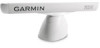
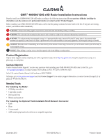
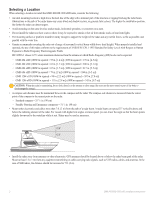
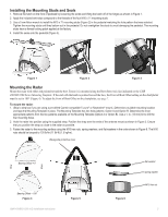
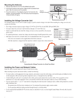
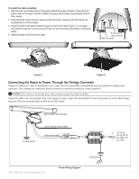
Installing the Mounting Studs and Seals 1. Remove the hatch on the front of pedestal by loosening the screw and lifting the hatch off of the hinges as shown in Figure 1. 2. Apply the included anti-seize compound to the threads of the four M10 x 71 mounting studs. 3. Use a 5 mm Allen wrench to install the M10 x 71 mounting studs (Figure 2) in the pedestal matching the hole pattern that was selected. Tighten the mounting studs until they bottom out in the pedestal. Do not overtighten the studs to avoid damaging the pedestal. The mounting studs have a thread-locking patch applied at the factory. 4. Install the seals onto the pedestal (Figure 3). Figure 1 Figure 2 Figure 3 Mounting the Radar Mount the radar with either end pointed toward the bow. Ensure it is mounted along the Bow-Stern Axis line indicated on the GMR 400/600/1200 Series Mounting Template. If the end with the hatch is pointed toward the bow, the Front of Boat Offset setting on the chartplotter must be set to 180° (Figure 4). To adjust the Front of Boat Offset on the chartplotter, see page 7. To mount the radar: 1. (Skip to step two if you are using a pre-drilled Garmin compatible Furuno® or Raymarine® mount.) Determine a suitable mounting location and tape the Mounting Template in place. The Mounting Template has two hole patterns: Option A and Option B. Determine the most appropriate patterns from the two patterns available on the Mounting Template (Option A or Option B). Use a 1/2 in. (13 mm) bit to drill the four mounting holes. 2. Hoist the radar into position using the supplied strap. Position the strap over the ends of the antenna mount as shown in Figure 5. Ensure that you position the strap as close to the radar as possible. 3. Fasten the radar to the mounting surface using the M10 hex nuts, spring washers, and flat washers in the order shown in Figure 6. The M10 nuts should be torqued to 130 lbf-in (11 lbf-ft) (1.5 kgf-m). Waveguide protective cover Bearing Offset = 0° Bow Stern Bearing Offset = 180° Figure 4 GMR 400/600/1200 xHD Installation Instructions Figure 5 Figure 6 flat washer spring washer M10 hex nut 3
-
 1
1 -
 2
2 -
 3
3 -
 4
4 -
 5
5 -
 6
6 -
 7
7 -
 8
8 -
 9
9 -
10
-
11
-
12
-
13
-
14
 |
 |