Garmin GNX 130 10-inch Large Format Marine Instrument Installation Instruction - Page 1
Garmin GNX 130 10-inch Large Format Marine Instrument Manual
 |
View all Garmin GNX 130 10-inch Large Format Marine Instrument manuals
Add to My Manuals
Save this manual to your list of manuals |
Page 1 highlights
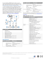
GNX™ 120/130 Installation Instructions Important Safety Information WARNING See the Important Safety and Product Information guide in the product box for product warnings and other important information. CAUTION Always wear safety goggles, ear protection, and a dust mask when drilling, cutting, or sanding. NOTICE When drilling or cutting, always check what is on the opposite side of the surface. Registering Your Device Help us better support you by completing our online registration today. • Go to http://my.garmin.com. • Keep the original sales receipt, or a photocopy, in a safe place. Contacting Garmin® Product Support • Go to http://www.garmin.com/support for in-country support information. • In the USA, call 913-397-8200 or 1-800-800-1020. • In the UK, call 0808 238 0000. • In Europe, call +44 (0) 870 850 1241. Tools Needed • Drill and drill bits ◦ 44 mm (1 3/4 in.) hole saw ◦ 4.5 mm (3/16 in.) drill bit • Marine sealant (recommended) Installing the Device Mounting Considerations NOTICE This device should be mounted in a location that is not exposed to extreme temperatures or conditions. The temperature range for this device is listed in the product specifications. Extended exposure to temperatures exceeding the specified temperature range, in storage or operating conditions, may cause device failure. Extreme-temperature-induced damage and related consequences are not covered by the warranty. The mounting surface must be flat to avoid damaging the device when it is mounted. When selecting a mounting location, observe these considerations. • The mounting location should be at or below eye level to provide optimal viewing as you operate your vessel. • The mounting surface must be strong enough to support the weight of the device and protect it from excessive vibration or shock. • To avoid interference with a magnetic compass, the device should not be installed closer to a compass than the compass-safe distance value listed in the product specifications. • The area behind the mounting surface must allow room for the routing and connection of the cables. Mounting the Device 1 Trim the flush-mount template and ensure it will fit in the location where you plan to mount the marine instrument. The flush-mount template is included in the product box. 2 Secure the template to the selected mounting location. 3 Using a 44 mm (1 3/4 in.) hole saw or rotary cutting tool, cut the hole in the center of the template. 4 Drill the 4.5 mm (3/16 in.) mounting holes. 5 Remove the remainder of the template. 6 Install the threaded rods in the back of the marine À instrument. 7 Place the included gasket on the back of the device. Á You should apply marine sealant around the gasket to prevent leakage behind the dashboard (recommended). 8 Place the marine instrument into the cutout .  9 Securely fasten the marine instrument from behind the mounting surface by tightening the supplied thumb nuts on à the threaded rods. 10Connect the NMEA 2000® drop cable and route it to your NMEA 2000 backbone. 11Snap the bezel into place. Connection Considerations The marine instrument connects to power and to data sources through a NMEA 2000 network. Although the instrument cannot directly receive NMEA® 0183 data, it can display NMEA 0183 data from sources connected to a GNX 20 or GNX 21 device (sold separately) on the same NMEA 2000 network. The instrument can also receive data from Nexus® instruments and sensors using a GND™ 10 device (sold separately). NMEA 2000 Connection Considerations NOTICE If you have an existing NMEA 2000 network on your boat, it should already be connected to power. Do not connect the NMEA 2000 power cable to an existing NMEA 2000 network, because only one power source should be connected to a NMEA 2000 network. March 2015 Printed in Taiwan 190-01846-02_0A
-
 1
1 -
 2
2
 |
 |