Garmin GNX 20 Marine Instrument Installation Instructions
Garmin GNX 20 Marine Instrument Manual
 |
View all Garmin GNX 20 Marine Instrument manuals
Add to My Manuals
Save this manual to your list of manuals |
Garmin GNX 20 Marine Instrument manual content summary:
- Garmin GNX 20 Marine Instrument | Installation Instructions - Page 1
GNX™ 20/21 Installation Instructions To obtain the best possible performance, install this marine instrument according to these instructions. If you experience difficulty during the installation, contact Garmin® Product Support, or seek the advice of a professional installer. This instrument - Garmin GNX 20 Marine Instrument | Installation Instructions - Page 2
marine instrument that currently uses a NMEA data cable, you do not need to purchase a new data cable, but you might need to replace the quarter-turn locking ring with a threaded locking ring. See your local Garmin dealer or www.garmin.com for more information. • The installation instructions - Garmin GNX 20 Marine Instrument | Installation Instructions - Page 3
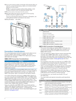
ground Tx This diagram is an example of a connection to a Garmin HVS GPS antenna. Item Description Marine instrument with a NMEA data cable (not included) À 12 Vdc power source Á Garmin HVS GPS antenna  Item Marine Instrument Wire Color N/A Black Yellow Blue White Brown Green Antenna Wire - Garmin GNX 20 Marine Instrument | Installation Instructions - Page 4
and other countries. GNX™ 20/21 is a trademark of Garmin Ltd. or its subsidiaries. These trademarks may not be used without the express permission of Garmin. NMEA®, NMEA 2000®, and the NMEA 2000 logo are registered trademarks of the National Marine Electronics Association. © 2014 Garmin Ltd. or its
-
 1
1 -
 2
2 -
 3
3 -
 4
4
 |
 |
GNX™ 20/21 Installation Instructions
To obtain the best possible performance, install this marine
instrument according to these instructions. If you experience
difficulty during the installation, contact Garmin
®
Product
Support, or seek the advice of a professional installer.
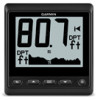
This instrument communicates with NMEA 2000
®
sensors and
devices, and shows information such as speed, heading, and
water depth when connected to the appropriate sensors. The
instrument can also communicate with a NMEA
®
0183 device
using an optional data cable.
Important Safety Information
WARNING
See the
Important Safety and Product Information
guide in the
product box for product warnings and other important
information.
CAUTION
Always wear safety goggles, ear protection, and a dust mask
when drilling, cutting, or sanding.
NOTICE
When drilling or cutting, always check what is on the opposite
side of the surface.
Registering Your Device
Help us better support you by completing our online registration
today.
•
Go to
.
•
Keep the original sales receipt, or a photocopy, in a safe
place.
Contacting Garmin Product Support
•
Go to
www.garmin.com/support
and click
Contact Support
for in-country support information.
•
In the USA, call (913) 397.8200 or (800) 800.1020.
•
In the UK, call 0808 2380000.
•
In Europe, call +44 (0) 870.8501241.
Mounting Considerations
NOTICE
This device should be mounted in a location that is not exposed
to extreme temperatures or conditions. The temperature range
for this device is listed in the product specifications. Extended
exposure to temperatures exceeding the specified temperature
range, in storage or operating conditions, may cause device
failure. Extreme-temperature-induced damage and related
consequences are not covered by the warranty.
The mounting surface must be flat to avoid damaging the device
when it is mounted.
Using the included hardware and template, you can flush mount
the device in the dashboard. If you want to mount the device
using an alternative method where it appears flat with the front
of the dashboard, you must purchase a flat-mount kit
(professional installation recommended) from your Garmin
dealer.
When selecting a mounting location, observe these
considerations.
•
The mounting location should be at or below eye level to
provide optimal viewing as you operate your vessel.
•
The mounting location should be at less than a 45° viewing
angle for the GNX 20 Marine Instrument with Standard LCD
and less than a 50° viewing angle for the GNX 21 Marine
Instrument with Inverted LCD. Screen color inversion occurs
when the viewing angle is greater than 30° in the 9 o'clock
direction on the GNX 20 and when the viewing angle is
greater than 60° in the 1 o'clock direction on the GNX 21.
•
The mounting location should allow easy access to the keys
on the device.
•
The mounting surface must be strong enough to support the
weight of the device and protect it from excessive vibration or
shock.
•
To avoid interference with a magnetic compass, the device
should not be installed closer to a compass than the
compass-safe distance value listed in the product
specifications.
•
The area behind the mounting surface must allow room for
the routing and connection of the cables.
Mounting the Device
NOTICE
If you are mounting the device in fiberglass, when drilling the
four pilot holes, it is recommended to use a countersink bit to
drill a clearance counterbore through only the top gel-coat layer.
This will help to avoid any cracking in the gel-coat layer when
the screws are tightened.
Stainless-steel screws may bind when screwed into fiberglass
and overtightened. Garmin recommends applying an anti-seize
lubricant to the screws before installing them.
The included template and hardware can be used to flush
mount the device in your dashboard. To mount the device so
the screen is flat with the dashboard, you must purchase a flat-
mount kit from your Garmin dealer.
1
Trim the flush-mount template and ensure it will fit in the
location where you plan to mount the marine instrument.
The flush-mount template is included in the product box.
2
Remove the liner from the adhesive on the back of the
template and apply it to the location where you plan to mount
the marine instrument.
3
If you plan to cut the hole with a jigsaw instead of a 90 mm
(3.5 in.) hole saw, use a 10 mm (
3
/
8
in.) drill bit to drill a pilot
hole to begin cutting the mounting surface.
4
Using the jigsaw or the 90 mm (3.5 in.) hole saw, cut the
mounting surface along the inside of the dashed line
indicated on the flush-mount template.
5
If necessary, use a file and sandpaper to refine the size of
the hole.
6
Place the marine instrument into the cutout to confirm that
the mounting holes on the template are in the correct
locations.
7
If the mounting holes are not correct, mark the correct
locations of the mounting holes.
8
Remove the marine instrument from the cutout.
9
Drill the 2.8 mm (
7
/
64
in.) pilot holes.
If you are mounting the marine instrument in fiberglass, use
a countersink bit as advised in the notice.
10
Remove the remainder of the template.
11
Place the included gasket on the back of the device and
apply marine sealant around the gasket to prevent leakage
behind the dashboard.
January 2014
190-01659-02_0A
Printed in Taiwan