Garmin GPS 24xd Receiver and Antenna Technical Reference for Garmin NMEA 2000 - Page 4
NMEA 2000 Network Planning and Construction, Linear Backbone Construction
 |
View all Garmin GPS 24xd Receiver and Antenna manuals
Add to My Manuals
Save this manual to your list of manuals |
Page 4 highlights
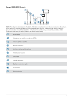
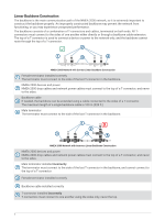
NMEA 2000 Network Planning and Construction The backbone is the main communication channel of an NMEA 2000 network to which your NMEA 2000 devices connect. You must connect each NMEA 2000 device to the backbone using a T-connector. You must connect the NMEA 2000 backbone to a power source, and you must install terminators at both ends of the network for proper functionality. When you design an NMEA 2000 network, you should start by creating a diagram of the network. When creating the diagram, be as detailed as possible, observing these considerations. • You should include all of the devices you intend to connect to the network. • You should note the approximate location on the boat for the backbone and each of the connected devices. • You should measure the distances between the location of each device and the backbone, and you should measure the overall length of the backbone. • You should note the power consumption (LEN) of each connected device. After you create a diagram of your network, you should apply the principles of proper NMEA 2000 network construction and adjust your plan as needed. You must understand and apply these concepts. • Linear backbone construction (Linear Backbone Construction, page 6) • Power connection and distribution (Power Connection Considerations, page 7) • Proper network termination (Network Termination, page 11) • Cable length and device limits (NMEA 2000 Cable Length and Device Limitations, page 12) 4
-
 1
1 -
 2
2 -
 3
3 -
 4
4 -
 5
5 -
 6
6 -
 7
7 -
 8
8 -
 9
9 -
 10
10 -
11
-
12
-
13
-
14
-
15
-
16
-
17
-
18
-
19
-
20
 |
 |
