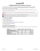
Garmin GPSMAP 527 Installation Instructions - Page 6
Installing the Wiring Harness
 |
View all Garmin GPSMAP 527 manuals
Add to My Manuals
Save this manual to your list of manuals |
Page 6 highlights
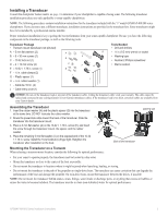
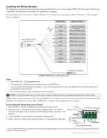
Installing the Wiring Harness The chartplotter comes with a wiring harness that connects the chartplotter to power and to optional NMEA 0183 and Garmin CANet devices. If applicable, the wiring harness also connects the chartplotter to a transducer. The wiring harness does not connect to a NMEA 2000 network. For instructions on connecting to a NMEA 2000 network with compatible devices, see page 8. Wire Color Wire Function To the GPSMAP 400/500 series chartplotter 3FAuse Red Black > Blue Brown > Grey Violet Power (10-32 Vdc*) Ground (power and NMEA 0183) NMEA 0183 port 1 Tx (out) NMEA 0183 port 1 Rx (in) NMEA 0183 port 2 Tx (out) NMEA 0183 port 2 Rx (in) > > Green White Orange Yellow CANet L (if applicable) CANet H (if applicable) Accessory on Alarm low To transducer (if applicable) GPSMAP 400/500 Series Wiring Harness Notes: • Use an AGC/ 3AG - 3 Amp replacement fuse. • If it is necessary to extend the power and ground wires, use 22 AWG wire. • You can wire the harness directly to the battery, or if your boat has an electrical system, you might be able to wire the harness to an unused holder on the fuse block. • Do not cut the transducer cable, because this voids your warranty. Notice: The maximum input voltage is 32 Vdc*. Do not exceed this voltage because this can damage the chartplotter and void the warranty. NOTE: During a typical installation, use only the red and black wires. The other wires do not have to be connected for normal operation of the chartplotter. For information on connecting to a NMEA 0183- or Garmin CANet-compatible device, see page 8. Connecting the Wiring Harness to Power 1. Use a test light or voltmeter to determine the polarity of the voltage source. 2. Connect the red (+ or positive) wire to the positive voltage terminal. (If you use the fuse block on the boat, route the positive connection through the fuse, as shown on the diagram.) 3. Connect the black (- or ground) wire to the negative voltage terminal. 4. Install or check the 3 A fuse (in the in-line fuse holder, or on the fuse block of the boat). 3 A fuse Boat ground - + To 10-32 Vdc* boat supply To device Fuse Block Example * Certain GPSMAP 400/500 series chartplotters can be connected to higher-voltage power sources. Refer to the Power section of the System Specifications on page 10 for more information. 6 GPSMAP 400/500 Series Installation Instructions
-
 1
1 -
 2
2 -
 3
3 -
 4
4 -
 5
5 -
 6
6 -
 7
7 -
 8
8 -
 9
9 -
 10
10 -
 11
11 -
 12
12
 |
 |
