Garmin GSR 56 Installation Manual
Garmin GSR 56 Manual
 |
View all Garmin GSR 56 manuals
Add to My Manuals
Save this manual to your list of manuals |
Garmin GSR 56 manual content summary:
- Garmin GSR 56 | Installation Manual - Page 1
GSR 56 Satellite Receiver Installation Manual 190-00836-00 August, 2010 Revision F - Garmin GSR 56 | Installation Manual - Page 2
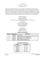
: 913.397.8200 Aviation Panel-Mount Technical Support Line (Toll Free) 1.888.606.5482 www.garmin.com Garmin (Europe) Ltd. Liberty House, Bulls Copse A Appendix B Page Range i - iv 1-1 - 1-8 2-1 - 2-2 3-1 - 3-6 4-1 - 4-4 A-1 - A-6 B-1 - B-2 Page A Revision F GSR 56 Installation Manual 190-00836-00 - Garmin GSR 56 | Installation Manual - Page 3
Material - special handling may apply, See www.dtsc.ca.gov./hazardouswaste/perchlorate. CURRENT REVISION DESCRIPTION Revision Page Number(s) F 3-5 Section Number 3.8 Description of Change Added Flight Data Services activation info GSR 56 Installation Manual 190-00836-00 Page i Revision F - Garmin GSR 56 | Installation Manual - Page 4
4.1 Pin Function List ...4-1 4.2 Power Functions...4-2 4.3 Serial Data...4-4 4.4 Audio Connections...4-4 4.5 Active Low Discrete Outputs...4-4 APPENDIX A OUTLINE AND INSTALLATION DRAWINGS A-1 APPENDIX B INTERCONNECT DRAWING B-1 Page ii Revision F GSR 56 Installation Manual 190-00836-00 - Garmin GSR 56 | Installation Manual - Page 5
for 011-02268-00 1-6 1-10 Non-TSO Functions ...1-7 1-11 Referenced Publications...1-7 2-1 Unit Part Numbers...2-1 2-2 Accessories...2-1 3-1 Pin Contact Part Numbers ...3-1 3-2 Recommended Crimp Tools ...3-1 3-3 Troubleshooting ...3-6 GSR 56 Installation Manual 190-00836-00 Page iii Revision F - Garmin GSR 56 | Installation Manual - Page 6
GSR 56. Mod Levels are listed with the associated service bulletin number, service bulletin date, and the purpose of the modification. The table is current at the time of publication of this manual (see date on front cover) and is subject to change without notice. Authorized Garmin Sales and Service - Garmin GSR 56 | Installation Manual - Page 7
(in rack) 1.2 Equipment Description The GSR 56 provides airborne low speed data link and voice communication capability to Garmin Integrated Flight Deck installations. The GSR 56 contains a transceiver that operates on the Iridium Satellite network. GSR 56 Installation Manual 190-00836-00 Page - Garmin GSR 56 | Installation Manual - Page 8
output and input channels to carry Iridium telephone audio to and from the GSR 56 Iridium transceiver(s). • Heater Configuration Pins: The GSR 56 contains an optional 30-W heater that must be configured for the particular system voltage of the installation. These pins provide a method to perform - Garmin GSR 56 | Installation Manual - Page 9
responsibility of the installing agency to obtain the latest revision of the GSR 56 Environmental Qualification Form. This form is available directly from Garmin under the following part number: GSR 56 (011-01706-00) Environmental Qualification Form, Garmin part number 005-00432-10 GSR 56 (011-02268 - Garmin GSR 56 | Installation Manual - Page 10
from the Iridium website at http://www.iridium.com are approved for use with the GSR 56. This list currently includes: 1. Comant CI 490-1 2. Sensor System S67-1575-165 3. Antcom S3IR16RR 4. Dayton Granger L10-780 5. Dayton Granger L10-787 Page 1-4 Revision F GSR 56 Installation Manual 190-00836 - Garmin GSR 56 | Installation Manual - Page 11
The GSR 56 system is limited to communication to the cockpit and cabin for convenience only. 1.6.1 TSO/ETSO Compliance 1.6.1.1 GSR 56 (011 Telecommunication Services (In Non Aeronautical Frequency Bands) TSO TSO-C139 ETSO-C50c ETSO-2C514 Category Class 2/Category 1 GSR 56 Installation Manual - Garmin GSR 56 | Installation Manual - Page 12
ED-14E/ RTCA DO-160E instead of ED-14D/ RTCA DO-160D as the environmental test standard. 2. Garmin was granted a deviation from ETSO-C50c § 3.1.1 to use RTCA DO-214 instead of EUROCAE ED-18/RTCA DO-170 as the Minimum Performance Standard. Page 1-6 Revision F GSR 56 Installation Manual 190-00836-00 - Garmin GSR 56 | Installation Manual - Page 13
10. Non-TSO Functions Function Iridium satellite radio transceiver Design Assurance RTCA/DO-178B Level E 1.7 Reference Documentation The publications listed in Table 1-11 are sources of additional information for installing the GSR 56. Before installing the GSR 56, the technician should read all - Garmin GSR 56 | Installation Manual - Page 14
East 151st Street Olathe, Kansas 66062, U.S.A. Phone: 913/397.8200 FAX: 913/397.0836 Garmin (Europe) Ltd. Liberty House, Bulls Copse Road Hounsdown Business Park Romsey, SO40 9RB, U.K. Phone: 44/ (0) 870.8501241 FAX: 44/ (0) 870.850125 Page 1-8 Revision F GSR 56 Installation Manual 190-00836-00 - Garmin GSR 56 | Installation Manual - Page 15
may be found useful for making retro-fit installations that comply with FAA regulations. Refer to the G1000 System Installation Manual, Garmin part number 190-00303-00 for further details on the mechanical aspects. 2.2 Installation Materials The GSR 56 is available as a single unit under the part - Garmin GSR 56 | Installation Manual - Page 16
from High-Intensity Radiation Fields (HIRF). The GSR 56 can be mounted using the GSR 56 remote rack shown in Figure 2-1. Refer to the Figure A-1 GSR 56 Outline and Installation Drawing for details. Figure 2-1. GSR 56 Remote Unit Rack Page 2-2 Revision F GSR 56 Installation Manual 190-00836-00 - Garmin GSR 56 | Installation Manual - Page 17
. Do not return the unit to Garmin until the carrier has authorized the claim Installation Allow adequate space for installation of cables and connectors. The installer shall supply and fabricate all of the cables. Electrical connections GSR 56 Installation Manual 190-00836-00 Page 3-1 Revision F - Garmin GSR 56 | Installation Manual - Page 18
used when reassembling the connector. 3. For applications using 16 AWG wire, contact Garmin for information regarding connector crimp positioner tooling. 3.3 Iridium Antenna Installation For use with the GSR 56, Iridium antennas have an operating frequency range of 1616-1626.5 MHz. Minimum antenna - Garmin GSR 56 | Installation Manual - Page 19
Iridium GSR 56 installations. 4. The Iridium antenna must be mounted on top of the aircraft for greatest satellite visibility (Figure 3-1). For best performance, select a location with an unobstructed view of the sky above the aircraft when in level flight. Location of communication antennas - Garmin GSR 56 | Installation Manual - Page 20
cable to the desired length and install TNC connectors at each end per the cabling instructions listed in Figure 3-2. For routing convenience, one end of the coaxial run can be terminated prior to installation. 3. With the GSR 56 receiver and antenna installed, route and clamp the coaxial cable - Garmin GSR 56 | Installation Manual - Page 21
GDL 59 Installation Manual, 190-00837-00. For actual aircraft installation/checkout, use only aircraft manufacturer approved checkout procedures. 3.8 Activation of Garmin Flight Data Services In order to activate the GSR 56 for Garmin Flight Data Services, please contact Garmin Product Support at - Garmin GSR 56 | Installation Manual - Page 22
output • Check wiring from GSR 56 to audio panel or GDL 59 • Verify subscription with Garmin Iridium Services • Verify subscription with Garmin Iridium Services Unable to make a phone call • Verify signal quality is adequate • Verify communication between GSR 56 and the display/control device - Garmin GSR 56 | Installation Manual - Page 23
GROUND 12 RS-232 OUT 13 RS-232 IN 14 SIGNAL GROUND 15 RESERVED 16 IRIDIUM REMOTE POWER ON* 17 POWER GROUND 18 RESERVED 19 POWER GROUND 20 RESERVED 21 1 34 AIRCRAFT POWER 2 *Denotes Active Low (Ground to activate) GSR 56 Installation Manual 190-00836-00 I/O Out Out -In In ------Out In --In ----In - Garmin GSR 56 | Installation Manual - Page 24
-- *Denotes Active Low (Ground to activate) 4.2 Power Functions 4.2.1 Aircraft Power The GSR 56 has four inputs pins for the two Aircraft Power busses of 14/28VDC. For 28V AIRCRAFT POWER 2 are "diode ORed" to provide power redundancy. Page 4-2 Revision F GSR 56 Installation Manual 190-00836-00 - Garmin GSR 56 | Installation Manual - Page 25
input conforming to: a) Low: 0 VDC < Vin < 3.5 VDC, OR Rin > 100k ohms (active) b) High: 8 VDC < Vin < 36 VDC (inactive) Pin Name IRIDIUM REMOTE POWER ON* *Denotes Active Low (Ground to activate) Connector Pin I/O P561 16 In GSR 56 Installation Manual 190-00836-00 Page 4-3 Revision F - Garmin GSR 56 | Installation Manual - Page 26
be externally limited to 20 mA max Pin Name STATUS DISCRETE* OUT *Denotes Active Low (Ground to activate) Connector Pin I/O P561 31 Out Page 4-4 Revision F GSR 56 Installation Manual 190-00836-00 - Garmin GSR 56 | Installation Manual - Page 27
DRAWINGS 011-01706-00 4.7 119 11.05 280.7 9.18 233.0 J561 6.96 176.8 3.3 83 2.08 52.8 1.220 30.99 .43 10.9 GSR 56 Installation Manual 190-00836-00 ANTENNA (TNC) 9.20 233.8 10.21 259.4 12.96 329.1 2.30 58.4 5.000 127.00 4X NOTE 3 1.0 26 NOTES: 1. DIMENSIONS: INCHES [mm] 2. - Garmin GSR 56 | Installation Manual - Page 28
DRAWINGS 011-02268-00 4.4 112 11.05 280.7 9.18 233.0 J561 6.96 176.8 3.5 89 2.08 52.8 1.220 30.99 .43 10.9 GSR 56 Installation Manual 190-00836-00 ANTENNA (TNC) 9.20 233.8 10.21 259.4 12.96 329.1 2.30 58.4 5.000 127.00 4X NOTE 3 1.1 28 NOTES: 1. DIMENSIONS: INCHES [mm] 2. - Garmin GSR 56 | Installation Manual - Page 29
APPENDIX A OUTLINE AND INSTALLATION DRAWINGS GSR 56 011-01706-00 OR GSR56 011-02268-00 GSR 56 Installation Manual 190-00836-00 CONNECTOR KIT 011-01732-00 CONFIGURATION MODULE (NOT SHOWN) 011-00979-00 RACK 115-01018-00 BACK PLATE SUB-ASSY 011-01800-00 Figure A-3. GSR 56 011-01706-00 and 011-02268 - Garmin GSR 56 | Installation Manual - Page 30
APPENDIX B INTERCONNECT DRAWING GSR 56 Installation Manual 190-00836-00 14 VDC HEATER POWER CONNECTIONS GSR 56 TRANSCEIVER P561 HEATER POWER 21 HEATER POWER 36 HEATER 1 LO 38 HEATER 1 HI 22 HEATER 2 HI 37 28 VDC HEATER POWER CONNECTIONS GSR 56 TRANSCEIVER P561 HEATER POWER 21
-
 1
1 -
 2
2 -
 3
3 -
 4
4 -
 5
5 -
 6
6 -
 7
7 -
8
-
9
-
10
-
11
-
12
-
13
-
14
-
15
-
16
-
17
-
18
-
19
-
20
-
21
-
22
-
23
-
24
-
25
-
26
-
27
-
28
-
29
-
30
 |
 |

190-00836-00
August, 2010
Revision F
GSR 56
Satellite Receiver
Installation Manual