Garmin VHF 215 AIS Technical Reference for Garmin NMEA 2000 Products - Page 5
Sample NMEA 2000 Network, Ignition or in-line switch and fuse
 |
View all Garmin VHF 215 AIS manuals
Add to My Manuals
Save this manual to your list of manuals |
Page 5 highlights
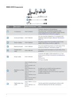
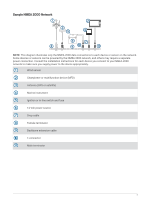
Sample NMEA 2000 Network NOTE: This diagram illustrates only the NMEA 2000 data connections to each device or sensor on the network. Some devices or sensors can be powered by the NMEA 2000 network, and others may require a separate power connection. Consult the installation instructions for each device you connect to your NMEA 2000 network to make sure you supply power to the device appropriately. Wind sensor Chartplotter or multifunction device (MFD) Antenna (GPS or satellite) Marine instrument Ignition or in-line switch and fuse 12 Vdc power source Drop cable Female terminator Backbone extension cable T-connector Male terminator 5
-
 1
1 -
 2
2 -
 3
3 -
 4
4 -
 5
5 -
 6
6 -
 7
7 -
 8
8 -
 9
9 -
 10
10 -
 11
11 -
12
-
13
-
14
-
15
-
16
-
17
-
18
-
19
-
20
 |
 |

Sample NMEA 2000 Network
NOTE:
This diagram illustrates only the NMEA 2000 data connections to each device or sensor on the network.
Some devices or sensors can be powered by the NMEA 2000 network, and others may require a separate
power connection. Consult the installation instructions for each device you connect to your NMEA 2000
network to make sure you supply power to the device appropriately.
Wind sensor
Chartplotter or multifunction device (MFD)
Antenna (GPS or satellite)
Marine instrument
Ignition or in-line switch and fuse
12 Vdc power source
Drop cable
Female terminator
Backbone extension cable
T-connector
Male terminator
5