GE 45231 User Manual - Page 9
yellow plug to the video jack and the white plug - c security cameras
 |
UPC - 431804523134
View all GE 45231 manuals
Add to My Manuals
Save this manual to your list of manuals |
Page 9 highlights
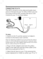
9 4. Run the 60' cable from the camera's location to the location of the TV, VCR or DVR. Use the cable clips provided to keep the cable in place. (See Notes on Cable Installation.) Do not run cable inside wall; Take care not to pierce, puncture or cut the cable when securing. 5. Connect the camera cable to the TV, VCR or DVR by connecting the 3-Wire adapter cable to the end of the 60 ft. cable coming from the camera. Locate the connector on the 3-Wire adapter labeled 'power' and plug in the AC adapter. Insert the yellow plug to the video jack and the white plug to the left/mono audio jack on the TV, VCR or DVR. 6. Adjustments can now be made to the camera viewing angle by loosening the adjustment knob and tilting and rotating the camera head.
-
 1
1 -
2
-
3
-
 4
4 -
 5
5 -
 6
6 -
 7
7 -
 8
8 -
 9
9 -
 10
10 -
 11
11 -
 12
12
 |
 |
