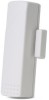
GE 60-886-95 Installation Instructions - Page 3
Reed Switch Setting, System Programming, RF Testing, Battery Replacement
 |
UPC - 782136700015
View all GE 60-886-95 manuals
Add to My Manuals
Save this manual to your list of manuals |
Page 3 highlights
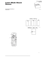
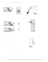
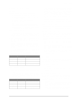
Reed Switch Setting Adjusting the Shock Sensor DIP Switches The following describes the DIP switch functions: ❑ DIP Switches 1 and 2-adjust the Pulse Count. ❑ DIP Switches 3 and 4-adjust the sensitivity setting of Gross Attack detection. ❑ DIP Switch 5-enable/disable reed switch. ❑ DIP Switch 6-not used. Note In order for the LED to indicate shock detection while adjusting the sensitivity, be sure the reed switch is disabled (DIP switch 5 OFF) or that the magnet is lined up with the reed switch if DIP switch 5 is ON. Gross Attack Adjustment 1. To adjust the sensor for Gross Attack, set DIP switches 1 and 2 to the ON position. This disables the Pulse Count so that the unit can only be activated by a Gross Attack. 2. Apply high level shocks to the mounting structure, using the LED as a guide to when the alarm trips (LED on for 4 seconds). The LED will blink for 1 second every time the sensor detects a pulse. A shock that is severe enough to cause an alarm will cause the LED to light for approximately 4 seconds. 3. Use switches 3 and 4 to adjust the Gross Attack sensitivity of the sensor (see Table 1). 4. Repeat step 2 each time you make a sensitivity change. Table 1: Gross Attack Sensitivity Settings DIP Switch 3 DIP Switch 4 Sensitivity OFF OFF 1 (maximum sensitivity) ON OFF 2 OFF ON 3 ON ON 4 (minimum sensitivity) Pulse Count Adjustment 1. Set the sensor to the desired Pulse Count (see Table 2). Note Pulse Count signals are counted at 1-second intervals and stored in a 30-second digital memory. These small signals can detect an intruder gently prying open a window or door frame. Table 2: Pulse Count Adjustment DIP Switch 1 DIP Switch 2 Pulse Count OFF OFF 4 ON OFF 6 OFF ON 8 ON ON Disabled 2. To test the pulse count setting, generate small shocks on the mounting structure. Each time a shock is detected, a pulse is registered in memory and the LED will blink for one second. If the programmed pulse count is reached within the most recent 30 seconds, the alarm will trip and the LED will light for approximately 4 seconds. If the alarm trips for any reason, the stored pulses are cancelled. 3. Use switches 1 and 2 to adjust the Pulse Count. 4. Repeat step 2 each time you make a sensitivity change. Reed Switch Setting After adjusting the sensor sensitivity, set DIP switch 5 to the appropriate setting, ON for enabled or OFF for disabled. System Programming This section describes the basic steps for adding the sensor to panel memory. Refer to the specific panel installation instructions for complete programming details. The reed switch must be enabled and open when learning the sensor. 1. With the cover on the sensor, set the panel to Program mode. 2. Proceed to the Learn Sensors menu. 3. Select the appropriate sensor group and sensor number assignments. 4. When prompted by the panel to trip the sensor, remove the sensor cover to activate the tamper switch. 5. Exit program mode. RF Testing This section describes the basic steps for testing the sensor. Refer to the specific panel or receiver installation instructions for complete testing details. 1. Set the panel to Sensor Test. 2. Trip the sensor. 3. Listen for appropriate response from system sirens. 4. Exit Sensor Test. Battery Replacement When the system indicates that the sensor has a low battery, remove the old battery and install a new battery (Duracell DL123A or a Sanyo CR123A) into the battery holder, observing proper polarity. Caution! Replace only with a Duracell DL123A battery or a Sanyo CR123A battery. Observe polarity when installing a new battery. Installing the battery backwards may cause damage to the sensor. Dispose of used batteries according to the manufacturer's instructions and/or local government authorities. 3
-
 1
1 -
 2
2 -
 3
3 -
 4
4
 |
 |
