GE AJCQ12ACD Use and Care Manual - Page 9
IMPORTANT, NOTICE, Safety Instructions, Care and Cleaning, Installation Instructions
 |
View all GE AJCQ12ACD manuals
Add to My Manuals
Save this manual to your list of manuals |
Page 9 highlights
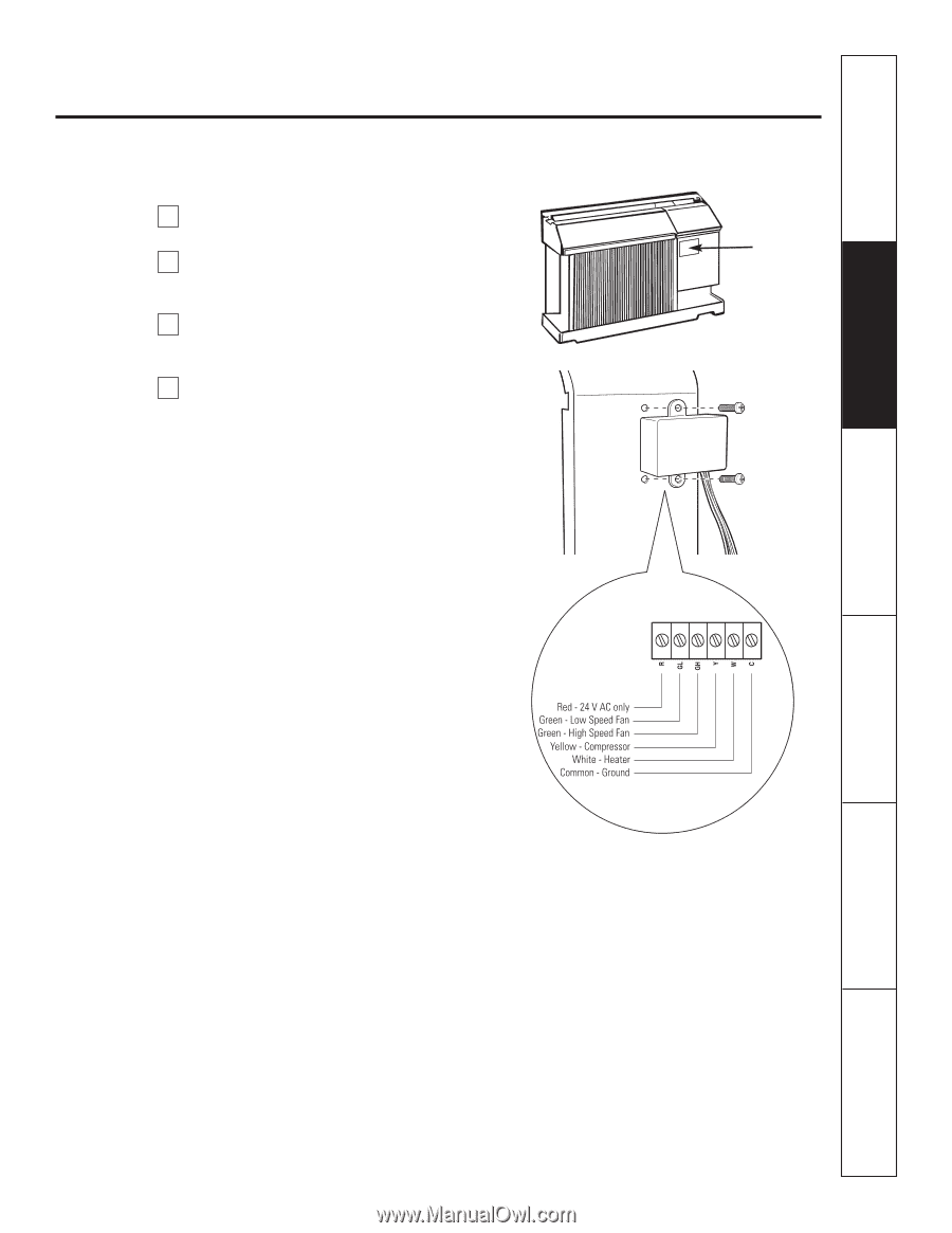
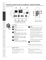
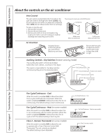
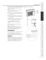
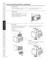
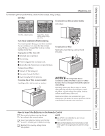
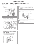
Safety Instructions Operating Instructions Care and Cleaning Installation Instructions Troubleshooting Tips Consumer Support GEAppliances.com Terminal Connections Remote Thermostat - Class 2 (on some models) The controls are located under a plastic cover behind the front grille. 1 Remove the front grille. See the Front Grille section of Care and Cleaning. 2 Remove the screws securing the plastic cover over the wiring connections. Set aside screws and plastic cover. 3 To make wiring connections, insert the wires into the bottom of the terminals and tighten screws securely. 4 After all desired connections have been made, replace the plastic cover and front grille. The owner is responsible for making all connections and setting the appropriate dip switches. When connected, the unit will be controlled by a remote thermostat. NOTE: The number 3 dip switch must be in the enabled (UP) position to activate the remote thermostat. (See the installation instructions supplied with the remote thermostat.) IMPORTANT: The thermostat connections provide 24 V AC only. If using a digital/electronic wall thermostat, ensure it is compatible with 24 VAC signal. See the Installation Instructions for the wall thermostat. NOTICE: Damage to a wall thermostat or to the electronics can result from improper connections. Special care must be used in connecting the wires. No line voltage connections should be made to any circuit. Isolate all wires in building from line voltage. Terminal connections location under front grille 9
-
 1
1 -
2
-
3
-
 4
4 -
 5
5 -
 6
6 -
 7
7 -
 8
8 -
 9
9 -
 10
10 -
 11
11 -
 12
12 -
 13
13 -
 14
14 -
15
-
16
-
17
-
18
-
19
-
20
-
21
-
22
-
23
-
24
-
25
-
26
-
27
-
28
-
29
-
30
-
31
-
32
-
33
-
34
-
35
-
36
-
37
-
38
-
39
-
40
-
41
-
42
-
43
-
44
-
45
-
46
-
47
-
48
-
49
-
50
-
51
-
52
-
53
-
54
-
55
-
56
-
57
-
58
-
59
-
60
-
61
-
62
-
63
-
64
-
65
-
66
-
67
-
68
-
69
-
70
-
71
-
72
 |
 |