GE DRSR495GGWW Installation Instructions - Page 3
Reconnecting Gas - installation
 |
UPC - 084691142300
View all GE DRSR495GGWW manuals
Add to My Manuals
Save this manual to your list of manuals |
Page 3 highlights
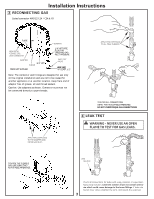
Installation Instructions 3 RECONNECTING GAS Listed connector ANSI Z21.24 / CSA 6.10 FLARE NPT 1/8" NPT PIPE PLUG FOR CHECKING GAS INLET PRESSURE 3/8" NPT PIPE SIZE AT LEAST 1/2" Note: The connector and fittings are designed for use only on the original installation and are not to be reused for another appliance or at another location. Keep flare end of adaptor free of grease, oil and thread sealant. Caution: Use adapters as shown. Connector nuts must not be connected directly to pipe threads. TIGHTEN ALL CONNECTIONS USING TWO ADJUSTABLE WRENCHES. DO NOT OVERTORQUE GAS CONNECTIONS! 4 LEAK TEST TIGHTEN THE FLEXIBLE GAS LINE USING TWO ADJUSTABLE WRENCHES. 3
-
 1
1 -
 2
2 -
 3
3 -
 4
4 -
 5
5 -
 6
6 -
 7
7 -
 8
8
 |
 |

3
4
LEAK TEST
Installation Instructions
3
RECONNECTING GAS
FLARE
NPT
PIPE SIZE
L
isted connector ANSI Z21.24 / CSA 6.10
Caution: Use adapt
e
rs as show
n
. Connector nuts must not
be
connected directly to pipe threads.
Note: The connector and fittings are designed for use only
on the original installation and are not to be reused for
another appliance or at another location. Keep flare end of
adaptor free of grease, oil and thread sealant.
1/8" NPT PIPE
PLUG FOR
CHECKING GAS
INLET PRESSURE
PIPE SIZE
AT LEAST 1/2"
3/8" NPT
TIGHTEN ALL CONNECTIONS
USING TWO ADJUSTABLE WRENCHES.
DO NOT OVERTORQUE GAS CONNECTIONS!
TIGHTEN THE FLEXIBLE
GAS LINE USING TWO
ADJUSTABLE WRENCHES.