GE GFDR485GFRR Quick Specs - Page 3
Dryer Exhausting Information - Metal Duct Only
 |
View all GE GFDR485GFRR manuals
Add to My Manuals
Save this manual to your list of manuals |
Page 3 highlights
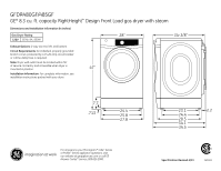
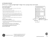
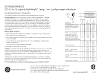
GFDR480GF/485GF GE® 8.3 cu. ft. capacity RightHeight™ Design Front Load gas dryer with steam Dryer Exhausting Information - Metal Duct Only For complete information, see installation instructions packed with your dryer. Ducting Materials: For best performance, this dryer should be vented with 4" diameter all rigid metal exhaust duct. If rigid metal duct cannot be used, then UL-listed flexible metal (semi-rigid) ducting can be used (Kit WX08X10077). In special installations, it may be necessary to connect the dryer to the house vent using a flexible metal (foil-type) duct. A UL-listed flexible metal (foil-type) duct may be used ONLY in installations where rigid metal or flexible metal (semi-rigid) ducting cannot be used AND where a 4" diameter can be maintained throughout the entire length of the transition duct. Please see installation instruction packed with your dryer for complete instructions when using flexible metal (foil type) ducting. Exhaust Length Calculation: 1. Determine the number of 90° turns needed for your installation. If you exhaust to the side or bottom of dryer, add one turn. 2. The maximum length of 4' rigid (aluminum or galvanized) duct which can be tolerated is shown in the table. A turn of 45° or less may be ignored. Two 45° turns within the duct length should be treated as a 90° elbow. A turn over 45° should be treated as a 90° elbow. Dryers must be exhausted to the outside. Caution: For personal safety do not terminate exhaust into a chimney, under any enclosed house floor (crawl space), or into an attic, since the accumulated lint could create a fire hazard or moisture could cause damage. Never terminate the exhaust into a common duct or plenum with a kitchen exhaust, since the combination of lint and grease could create a fire hazard. Exhaust ducts should be terminated in a dampered wall cap to prevent back drafts, bird nesting, etc. The wall cap must also be located at least 12" above the ground or any other obstruction with the opening pointed down. For more information on venting kits and accessories, please call 1-800-GE-CARES. A A 4 Best performance Maximum length of 4" dia. rigid metal duct Exhaust hood type B Domestic 2-1/2 dryer models All Long Vent 6.0 - 8.0 cu. ft. capacity (GE & Profile models) electric & gas dryers (GTDL, DLSR, PFDS Number of 90° turns 0 1 2 3 4 5 A 4" opening 150 ft. 135 ft. 125 ft. 115 ft. 105 ft. 95 ft. B 2 -1/2" opening 125 ft. 115 ft. 105 ft. 95 ft. 85 ft. 75 ft. All 6.0 - 8.3 cu. ft. capacity 0 models electric and gas 1 dryers (GFDS, GFDR, GFDN, 2 DCVH5, DCVH, GTDS, GLDS, 3 GRDN, GTDN, GHDN, GHDS, 4 GTDP, GLDP, GTDX, HTDP, HTDX 90 ft. 60 ft. 45 ft. 35 ft. 25 ft. 60 ft. 45 ft. 35 ft. 25 ft. 15 ft. DCVH480, DCVH485 0 90 ft. 60 ft. 1 60 ft. 45 ft. 2 45 ft. 35 ft. 3 35 ft. 25 ft. All 3.6 cu. ft. (DSKS, DSKP) electric dryers Laundry Center GTUP270, GTUN275 0 46 ft. 37 ft. 1 37 ft. 30 ft. 2 30 ft. 22 ft. 3 23 ft. 15 ft. 0 56 ft. 42 ft. 1 48 ft. 34 ft. 2 40 ft. 26 ft. 3 32 ft. 18 ft. Laundry Center GTUP240 0 43 ft. 36 ft. 1 33 ft. 26 ft. 2 24 ft. 16 ft. For every extra 90° elbow, reduce the allowable vent system length by 10 ft. Two 45° elbows will be treated like one 90° elbow. For the side exhaust installations, add one 90° elbow to the chart. The total vent system length includes all the straight portions and elbows of the system (transition duct included). Specification Revised 4/13 360502
-
 1
1 -
 2
2 -
 3
3 -
 4
4
 |
 |
