GE GFDS175EHDG Installation Instructions
GE GFDS175EHDG Manual
 |
View all GE GFDS175EHDG manuals
Add to My Manuals
Save this manual to your list of manuals |
GE GFDS175EHDG manual content summary:
- GE GFDS175EHDG | Installation Instructions - Page 1
metal (semi-rigid or foil-type) duct is installed, it must be UL-listed and installed in accordance with the instructions found in "Connecting the Dryer to House Vent" later in this manual. Flexible vent materials are known to collapse, be easily crushed and trap lint. These conditions will obstruct - GE GFDS175EHDG | Installation Instructions - Page 2
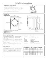
.8cm) 39.3" (99.8 cm) NOTE: Dryer height can be adjusted to match washer height With Pedestal: 52.1" (132.33 cm) Stacked: 84" (213.36 cm) Side View 5.4" (13.7 cm) 4.4" (11.2 cm) STEAM WATER HOSES: GE strongly recommends the use of factory specified parts. These hoses are manufactured and tested - GE GFDS175EHDG | Installation Instructions - Page 3
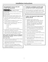
service. MOBILE OR MANUFACTURED HOME INSTALLATION • Installation must conform to the MANUFACTURED HOME CONSTRUCTION AND SAFETY STANDARD, TITLE 24, PART home. • The vent duct material MUST BE METAL. • KIT 14-D346-33 MUST be used to attach the dryer securely to the structure. • The vent MUST NOT be - GE GFDS175EHDG | Installation Instructions - Page 4
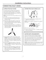
Installation Instructions CONNECTING INLET HOSES CONNECTING INLET HOSES To produce steam, the dryer must connect to the cold hand until firmly seated. 5. Ensure the rubber flat washer is in place and attach the dryer's long inlet hose to the other male end of the ''Y'' connector. Tighten by hand - GE GFDS175EHDG | Installation Instructions - Page 5
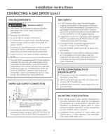
Installation Instructions CONNECTING A GAS DRYER (skip for electric dryers) TOOLS YOU WILL NEED ˆ10" Adjustable wrenches (2) ˆ Flat-blade screwdriver Before beginning the installation, turn off the circuit breaker(s) or remove the dryer's circuit fuse(s) at the electrical box. Be sure the dryer - GE GFDS175EHDG | Installation Instructions - Page 6
Installation Instructions CONNECTING A GAS DRYER (cont.) GAS REQUIREMENTS WARNING - Explosion Hazard • Use a • This gas dryer is equipped with a Valve & Burner Assembly for use only with natural gas. Using conversion kit WE25X0217, your local service organization can convert this dryer for use with - GE GFDS175EHDG | Installation Instructions - Page 7
Installation Instructions CONNECTING THE DRYER TO THE GAS SUPPLY A Install a female 3/8" NPT elbow at the end of the dryer gas inlet. Install a 3/8" flare union adapter to the female elbow. IMPORTANT: Use a pipe wrench to securely hold on to the end of the dryer gas inlet to prevent twisting the - GE GFDS175EHDG | Installation Instructions - Page 8
Installation Instructions CONNECTING A GAS DRYER (cont.) TEST FOR LEAKS Never use an open flame to , retighten the joint and repeat the soap test. ELECTRICAL CONNECTION INFORMATION FOR GAS DRYERS (cont.) The dryer must be electrically grounded in accordance with local codes, or in the absence of - GE GFDS175EHDG | Installation Instructions - Page 9
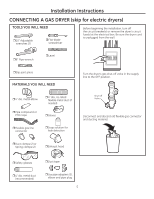
spring clamps (2) ˆ Duct tape ˆ Safety glasses ˆ 4" dia. metal duct (recommended) ˆ 4" dia., UL-listed flexible metal duct (if needed) ˆ Dryer power cord kit (not provided with dryer) UL rated 120/240V, 30A with 3 or 4 prongs. Identify the plug type as per the house receptacle before purchasing - GE GFDS175EHDG | Installation Instructions - Page 10
result in death, fire or electrical shock. GROUNDING INSTRUCTIONS For a grounded, cord-connected dryer: This dryer must be grounded. In the event of a risk of electrical shock. Check with a qualified electrician, or service representative or personnel, if you are in doubt as to whether - GE GFDS175EHDG | Installation Instructions - Page 11
Instructions CONNECTING DRYER USING 4-WIRE CONNECTION (MUST BE USED FOR MOBILE HOME INSTALLATION) NOTE: Since January 1, 1996, the National Electrical Code requires that new constructions use a 4-wire connection to an electric dryer power supply cord kit marked for use with dryers and provided with - GE GFDS175EHDG | Installation Instructions - Page 12
Instructions EXHAUSTING THE DRYER WARNING - Fire Hazard This dryer MUST be vented to the outdoors. Use only 4" rigid metal ducting for the home exhaust duct. Use only 4" rigid metal or UL-listed dryer transition duct to connect the dryer ducting can be used (Kit WX08X10077). • Never install - GE GFDS175EHDG | Installation Instructions - Page 13
Instructions dryer life. • Accumulate lint, creating a potential fire hazard. The correct exhaust installation is YOUR RESPONSIBILITY. Problems system (transition duct included). EXHAUST LENGTH FOR LONG VENT MODEL - GFDL110 RECOMMENDED MAXIMUM LENGTH Exhaust Hood Types Recommended Use - GE GFDS175EHDG | Installation Instructions - Page 14
Installation Instructions EXHAUSTING THE DRYER (cont.) EXHAUST SYSTEM CHECKLIST HOOD OR WALL CAP • Terminate be tight to avoid leaks. The male end of each section of duct must point away from the dryer. • Duct joints should be made air- and moisture-tight by wrapping the overlapped joints with duct - GE GFDS175EHDG | Installation Instructions - Page 15
Instructions SIDE OR BOTTOM VENTING Dryer Exhaust to right of cabinet for Electric models only. Dryer Exhaust to left of cabinet for Gas and Electric models. Dryer Exhaust to the bottom of cabinet for Gas and Electric models. WARNING - Fire Hazard Close the back opening with cover plate (Kit - GE GFDS175EHDG | Installation Instructions - Page 16
to complete the exhaust system. Cover back opening with a plate (Kit WE1M454) available from your local service provider. Place dryer in final location. NEVER LEAVE THE BACK OPENING WITHOUT THE PLATE. (Kit WE1M454.) NOTE: If the dryer has been exposed to temperatures below freezing for an extended - GE GFDS175EHDG | Installation Instructions - Page 17
instalación Secadora Si tiene alguna pregunta, llame a 800.GE.CARES (800.432.2737) o visite nuestro sitio Web las instrucciones de "Cómo conectar la secadora a la ventilación doméstica" de este manual. Los materiales de los conductos flexibles a menudo se desploman, se aplastan y atrapan pelusas - GE GFDS175EHDG | Installation Instructions - Page 18
son fabricadas y probadas de modo que se cubran las especificaciones de GE. GE recomienda enfáticamente el uso de nuevas mangueras de suministro de agua. Pieza WE25M53 O WE1M847 WE1M848 PM14X10056 puerta incluido) WX14X10007 Accesorio Kit Completo (mangueras, lavadora con adaptador en Y) (incluido) - GE GFDS175EHDG | Installation Instructions - Page 19
es: 0" sobre ambos lados 3" sobre el frente 3" sobre el la parte trasera 52" desde la puerta hasta los gabinetes sobre ésta • Se deber • El material del conducto de ventilación DEBE SER METAL. • DEBE utilizarse el KIT 14-D346-33 para conectar bien la secadora a la estructura. • La ventilaci - GE GFDS175EHDG | Installation Instructions - Page 20
goma se encuentre en su lugar y sujete el otro extremo de la manguera larga de entrada al conector de la válvula de llenado en la parte inferior del panel trasero de la secadora. Ajuste a mano hasta que esté firmemente asentada. REQUISITOS DE SUMINISTRO DE AGUA Los grifos de agua caliente y fr - GE GFDS175EHDG | Installation Instructions - Page 21
Instrucciones de instalación CÓMO CONECTAR UNA SECADORA A GAS (si se cuenta con una secadora eléctrica, saltear este paso) HERRAMIENTAS NECESARIAS ˆLlaves ajustables de 10" (2) ˆ Destornillador de lados planos Antes de comenzar la instalación, apague el disyuntor o quite los fusibles de la - GE GFDS175EHDG | Installation Instructions - Page 22
válvula y quemador para utilizar sólo con gas natural. Mediante el kit de conversión WE25X0217, la organización de atención local puede convertir NPT DE 3/8" NOTA: Agregue a la dimensión vertical la distancia entre la parte inferior del gabinete y el piso. • Debe utilizar un conector flexible metá - GE GFDS175EHDG | Installation Instructions - Page 23
Instrucciones de instalación CÓMO CONECTAR LA SECADORA AL SUMINISTRO DE GAS A Instale un codo hembra NPT de 3/8" al final de la entrada de gas de la secadora. Instale un adaptador de unión cónica de 3/8" al codo hembra. IMPORTANTE: Utilice una llave para tubos para sostener bien el extremo de la - GE GFDS175EHDG | Installation Instructions - Page 24
lo permiten, se podrá agregar un cable a tierra externo (no provisto), ajustando el mismo al tornillo conectado a tierra de color verde en la parte trasera de la secadora, y a una conexión cañería metálica de agua fría conectada a tierra u otra conexión a tierra establecida. Tornillo de conexi - GE GFDS175EHDG | Installation Instructions - Page 25
ˆGafas de seguridad ˆConducto de metal de 4" de diámetro (recomendado) ˆConducto de metal flexible de 4" de diámetro (si fuese necesario) ˆCinta aislante ˆKit de cable de energía de la secadora (no incluido con la secadora) Clasificado UL, de 120/240V, 30A con 3 o 4 patas. Identifique el tipo de - GE GFDS175EHDG | Installation Instructions - Page 26
Instrucciones de instalación CÓMO CONECTAR UNA SECADORA ELECTRICA (cont.) CONEXIÓN ELÉCTRICA INFORMACIÓN SOBRE LAS SECADORAS ELÉCTRICAS Para realizar conexiones eléctricas con un cable de corriente: ADVERTENCIA - Riesgo de incendio Use un cable de suministro de corriente de la secadora de 30 - GE GFDS175EHDG | Installation Instructions - Page 27
de alivio de tensión 3 conductores de cobre #10 AWG mínimo o kit de cable de suministro de energía de 120/240V 30A marcado para su del tomacorriente. 3. Quite la tapa del cable de energía ubicada en la parte trasera inferior. 4. Instale un alivio de tensión de 3/4 pulgadas reconocido por UL - GE GFDS175EHDG | Installation Instructions - Page 28
un conducto de metal flexible (semi-rígido) de la lista de UL (Kit WX08X10077). • Nunca instale un conducto de metal flexible en paredes, cielos rasos, Conductos de Transición para Secadoras de Ropa" (Outline for Clothes Dryer Transition Duct Subject 2158A). • Nunca instale un conducto de metal - GE GFDS175EHDG | Installation Instructions - Page 29
Instrucciones de instalación • CORTE el conducto lo más corto posible e instálelo derecho en la pared. • UTILICE codos cuando hagan falta curvas. Coudes • NO doble o pliegue los conductos. Utilice codos si algunos codos resultan necesarios. • NO utilice una longitud de salida excesiva. Corte - GE GFDS175EHDG | Installation Instructions - Page 30
por lo menos a 12" sobre el nivel del suelo o cualquier otra obstrucción con la abertura apuntando hacia abajo. • Nunca ventile la secadora en la parte exterior del techo. SEPARACIÓN DE CURVAS • Para un mejor desempeño, separe todas las curvas con 4 pies de conducto recto como mínimo, incluyendo la - GE GFDS175EHDG | Installation Instructions - Page 31
de incendio Cierre la abertura trasera con la placa protectora (Kit WE1M454). Desconecte la secadora del suministro eléctrico. Use laceraciones. Derecha (sólo modelos a eléctrico) Quite el tornillo y consérvelo Parte inferior Izquierda Quite la tapa deseada (sólo una) UBICACIÓN DE LA LENGÜETA - GE GFDS175EHDG | Installation Instructions - Page 32
la secadora se encuentre nivelada de lado a lado y del frente a la parte trasera. Elevar Bajar 2 ENCHUFE LA SECADORA Verifique que haya una conexión a final. NUNCA DEJE LA ABERTURA TRASERA SIN LA PLACA EN SU LUGAR. (Kit WE1M454.) NOTA: Si la secadora ha sido expuesta a temperaturas bajo cero por
-
 1
1 -
 2
2 -
 3
3 -
 4
4 -
 5
5 -
 6
6 -
 7
7 -
8
-
9
-
10
-
11
-
12
-
13
-
14
-
15
-
16
-
17
-
18
-
19
-
20
-
21
-
22
-
23
-
24
-
25
-
26
-
27
-
28
-
29
-
30
-
31
-
32
 |
 |
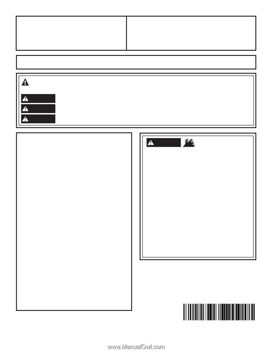
BEFORE YOU BEGIN
Read these instructions completely and carefully.
•
IMPORTANT
–
Save these instructions for local
electrical inspector’s use.
•
IMPORTANT
–
Observe all governing codes and
ordinances.
•
Install the clothes dryer according to the manufacturer’s
instructions and local codes.
•
Note to Installer –
Be sure to leave these instructions
with the Consumer.
•
Note to Consumer –
Keep these instructions for future
reference.
•
Clothes dryer installation must be performed by a
qualified installer.
•
This dryer
must
be exhausted to the outdoors.
•
Before the old dryer is removed from service or
discarded, remove the dryer door.
•
Service information and the wiring diagram are located
in the control console.
•
Do not allow children on or in the appliance. Close
supervision of children is necessary when the appliance
is used near children.
•
Proper installation is the responsibility of the installer.
•
Product failure due to improper installation is not
covered under the Warranty
.
•
Install the dryer where the temperature is above 50°F
for satisfactory operation of the dryer control system.
• Remove and discard existing plastic or metal foil duct
and replace with UL-listed duct.
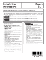
Questions? Call 800.GE.CARES (800.432.2737) or visit our Web site at: GEAppliances.com
- Fire Hazard
WARNING
•
Clothes dryer installation must be performed by a
qualified installer.
•
Install the clothes dryer according to these
instructions and local codes.
•
DO NOT
install a clothes dryer with flexible plastic
venting materials. If flexible metal (semi-rigid or
foil-type) duct is installed, it must be UL-listed and
installed in accordance with the instructions found
in “Connecting the Dryer to House Vent” later in
this manual. Flexible vent materials are known to
collapse, be easily crushed and trap lint. These
conditions will obstruct dryer airflow and increase
the risk of fire.
•
DO NOT
install or store this appliance in any
location where it could be exposed to water or
weather.
•
To reduce the risk of severe injury or death, follow
all installation instructions.
•
Save these instructions. (Installers: Be sure to leave
these instructions with the customer.)
Installation
Dryers
Instructions
01
This is the safety alert symbol. This symbol alerts you to potential hazards that can kill you or hurt you and others.
All safety messages will follow the safety alert symbol and the word “DANGER”, “WARNING”, or “CAUTION”. These
words are defined as:
Indicates a hazardous situation which, if not avoided,
will
result in death or serious injury.
Indicates a hazardous situation which, if not avoided,
could
result in death or serious injury.
Indicates a hazardous situation which, if not avoided,
could
result in minor or moderate injury.
DANGER
WARNING
CAUTION
31-16748
04-14
GE
234D2274P001
Printed in Mexico