GE JB620SRSS Installation Instructions
GE JB620SRSS Manual
 |
UPC - 084691224396
View all GE JB620SRSS manuals
Add to My Manuals
Save this manual to your list of manuals |
GE JB620SRSS manual content summary:
- GE JB620SRSS | Installation Instructions - Page 1
USE ONLY) See illustrations for all rough-in and spacing dimensions. The range may be placed with 0" clearance (flush) at the back wall and side walls of the cabinet. SINGLE OVEN DOUBLE OVEN On models with baking or warming drawers, electrical outlet must not be in this area. 21⁄2" * 297⁄8" 47 - GE JB620SRSS | Installation Instructions - Page 2
beginning installation. We recommend you have the electrical wiring and hookup of your range connected by a qualified electrician. After installation of range) by removing screws using a 1/4" nut driver. Do not discard these screws. SINGLE OVEN DOUBLE OVEN Back of range Back of range Retaining - GE JB620SRSS | Installation Instructions - Page 3
neutral) wire tip through the bottom center terminal block opening. On certain models, the wire will need to be inserted through the ground strap opening wire terminal ring, through the ground plate and into the frame of the range. C. Insert the 3 terminal screws (removed earlier) through each power - GE JB620SRSS | Installation Instructions - Page 4
MODELS WITH STORAGE DRAWER OR KICK PANELS A Plug in unit and slide into place. Pull drawer out until it stops. B Lift front of drawer until the stops clear the guide. Remove the drawer. C Install the oven shelves in the oven and position the range see the Owner's Manual for proper replacement. • - GE JB620SRSS | Installation Instructions - Page 5
de empaque puede provocar daños al electrodoméstico. Quite todas las partes de empaque del horno, bandejas, elementos calentadores y cajón. También, quite la longitud sea paralela al piso. 253⁄8" 45" * Los modelos de marca GE cuentan con paneles de control de un ancho de 30-7⁄8". NOTA: Utilice un - GE JB620SRSS | Installation Instructions - Page 6
trasera de la cocina) quitando tornillos mediante una llave de tuercas de 1/4". No elimine esos tornillos. HORNO SIMPLE HORNO DOBLE Parte trasera de la cocina Parte trasera de la cocina Lengüetas de retención 5 tornillos para quitar la tapa del cable Tornillo para quitar la tapa del bloque - GE JB620SRSS | Installation Instructions - Page 7
5 INSTALACIÓN DE TRES (3) ALAMBRES ADVERTENCIA: El cable neutral o a tierra del cable de energía debe estar conectado a la terminal neutral ubicada en el centro del bloque terminal y la cinta de conexión a tierra debe conectar la terminal neutral a la placa de conexión a tierra. Los cables de energ - GE JB620SRSS | Installation Instructions - Page 8
esté instalado y adosado correctamente, retire el cajón de almacenaje o la parte inferior delantera y observe debajo de la cocina que la pata niveladora esté y que los dos funcionen correctamente. Si no es así, consulte el Manual del propietario para un reemplazo adecuado. • Controle que la pata de
-
 1
1 -
 2
2 -
 3
3 -
 4
4 -
 5
5 -
 6
6 -
 7
7 -
8
 |
 |

BEFORE YOU BEGIN
Read these instructions completely and
carefully.
•
IMPORTANT —
Save these
instructions for local inspector’s use.
•
IMPORTANT —
Observe all
governing codes and ordinances.
•
Note to Installer –
Be sure to leave these
instructions with consumer.
•
Note to consumer –
Keep these
instructions for future reference.
•
Skill level –
Installation of this appliance
requires a qualified installer or electrician.
•
Proper installation is the responsibility of the
installer.
•
Product failure due to improper installation is
not covered under warranty.
FOR YOUR SAFETY:
If you did not receive an anti-tip bracket with your purchase,
call 1-800-626-8774 to receive one at no cost. (In Canada,
call 1-800-561-3344.) For installation instructions of the bracket,
visit: www.geappliances.com. (In Canada, www.geappliances.ca.)
Installation Instructions
Free-Standing Electric Ranges
MATERIALS YOU MAY NEED
TOOLS YOU WILL NEED
Anti-Tip Bracket
Kit Included
(UL Listed 40 AMP)
4-Wire Cord 4‘ long
OR
3-Wire Cord 4‘ long
Squeeze Connector
(For Conduit
Installations Only)
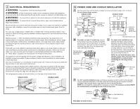
REMOVE PACKAGING MATERIALS:
Failure to remove packaging
materials could result in damage to the appliance. Remove all packing parts from oven,
racks, heating elements and drawer. Also, remove protective film and labels on the outer
door, cooktop and control panel.
1
Drill with 1/8” Bit
Safety Glasses
Adjustable Wrench
Level
Tin Snips
Tape Measure
Pliers
1/4” Nut Driver
Questions?
Call 1-800-GE-CARES (1-800-432-2737) or visit www.geappliances.com
In Canada, call 1-800-
561-3344
or visit www.geappliances.ca
WARNING
—
Before
beginning the installation, switch
power off at service panel and
lock the service disconnecting
means to prevent power from
being switched on accidentally.
When the service disconnecting
means cannot be locked,
securely fasten a prominent
warning device, such as a tag,
to the service panel.
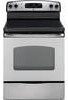
PREPARE THE OPENING (FOR INDOOR USE ONLY)
See illustrations for all rough-in and spacing dimensions. The range may be placed with 0”
clearance (flush) at the back wall and side walls of the cabinet.
2
2
1
⁄
2
”
2
1
⁄
2
”
7
1
⁄
2
”
25”
47
”
25
3
⁄
8
”
7”
14
1
⁄
2
”
On models with baking
or warming drawers,
electrical outlet must
not be in this area.
3
1
⁄
4
”
3
1
⁄
4
”
7
3
⁄
4
”
23
1
⁄
2
”
47”
29
7
⁄
8
”
25
3
⁄
8
”
45”
36”
SINGLE OVEN
DOUBLE OVEN
A
NOTE C
B
A
C
Both
Sides
NOTE:
Use a 4
′
power cord to prevent interference
with the storage drawer. Power cords 4
1
⁄
2
to 6
′
long
may have to be dressed to allow for proper drawer
closing.
MINIMUM DIMENSIONS BETWEEN COOKTOP,
WALLS AND ABOVE THE COOKTOP:
A.
Make sure the wall covering, countertop, flooring
and cabinets around the range can withstand
the heat (up to 200°F) generated by the range.
B.
Allow 30” minimum clearance between surface
units and bottom of unprotected wood or metal
cabinet, or allow a 24” minimum when bottom of
wood or metal cabinet is protected by no less
than 1/4” thick flame retardant millboard covered
with not less than No 28 MSG sheet metal,
(.015”), .015” thick stainless steel, .024”
aluminum or .020” copper.
Acceptable electrical outlet area.
Orient electrical receptacle so the
length is parallel to floor.
*
GE-branded models have control
panels 30-
7⁄8” wide.
30”
47
5
⁄
8
”
30”
C.
This appliance has been approved for 0” spacing to adjacent surfaces above the cooktop.
However, a 6” minimum spacing to surfaces less than 15” above the cooktop and adjacent
cabinet is recommended to reduce exposure to steam, grease splatter and heat.
To reduce the risk of burns or fire when reaching over hot surface elements, cabinet storage
space above the cooktop should be avoided. If cabinet storage space is to be provided above the
cooktop, the risk can be reduced by installing a range hood that projects at least 5” beyond the
front of the cabinets. Cabinets installed above the cooktop must be no deeper than 13”.
29
7
⁄
8
”
*
*
4”
4”