GE JB620SRSS Installation Instructions - Page 4
Replace The Wire Cover, Anti-tip Device Installation, Level The Range, Warning, Final Installation - owners manual
 |
UPC - 084691224396
View all GE JB620SRSS manuals
Add to My Manuals
Save this manual to your list of manuals |
Page 4 highlights
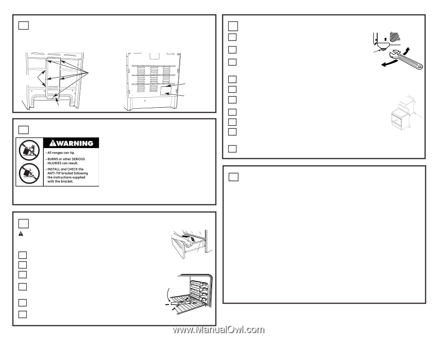
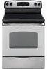
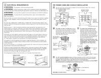
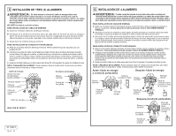
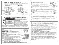
7 REPLACE THE WIRE COVER Replace wire cover on range back by sliding its left edge under the retaining tabs and replace the screws removed earlier. Make sure that no wires are pinched between cover and range back. SINGLE OVEN DOUBLE OVEN Back of range Back of range Retaining tabs 5 screws to remove wire cover Wire cover Screw to remove terminal block cover Terminal block cover 8 ANTI-TIP DEVICE INSTALLATION To reduce the risk of tipping the range, the range must be secured by a properly installed anti-tip bracket. See installation instructions shipped with the bracket for complete details before attempting to install. To check if the bracket is installed and engaged properly, remove the storage drawer or kick panel and look underneath the range to see that the leveling leg is engaged in the bracket. On models without a storage drawer or kick panel, carefully tip the range forward. The bracket should stop the range within 4 inches. If it does not, the bracket must be reinstalled. If the range is pulled from the wall for any reason, always repeat this procedure to verify the range is properly secured by the anti-tip bracket. Never completely remove the leveling legs or the range will not be secured to the anti-tip device properly. 9 LEVEL THE RANGE WARNING: Never completely remove the leveling leg as the range will not be secured to the anti-tip device properly. MODELS WITH STORAGE DRAWER OR KICK PANELS A Plug in unit and slide into place. Pull drawer out until it stops. B Lift front of drawer until the stops clear the guide. Remove the drawer. C Install the oven shelves in the oven and position the range where it will be installed. D Check for levelness by placing a spirit level on one of the oven shelves. Take two readings-with the level placed diagonally first in one direction and then the other. E The front leveling legs can be adjusted from the bottom and the rear legs can be adjusted from the top or the bottom. F Use an adjustable wrench to adjust the leveling legs until the range is level. Stop 9 LEVEL THE RANGE (CONT.) G Position cord so that it does not interfere with drawer. Place drawer rail on guides. Push the drawer in until it stops. H Lift front of drawer and push in until the stops clear the guides. Leg leveler I Lower the front of the drawer and push in until it closes. MODELS WITH BAKING, WARMING DRAWERS OR DOUBLE OVEN A Plug in the unit. Lower range Raise range B Measure the height of your countertop at the rear of the opening (X). C Adjust two rear leveling legs so that the rear of cooktop is at the same height as the counter (Y). D Slide unit into place. E Install oven shelves in the oven and position the range where it will be installed. X Y F Check for levelness by placing a spirit level on one of the oven shelves. Take two readings-with the level placed diagonally first in one direction and then the other. G Adjust front leveling legs until the range is level. 10 FINAL INSTALLATION CHECKLIST • Check to make sure the circuit breaker is closed (RESET) or the circuit fuses are replaced. • Be sure power is in service to the building. • Check that all packing materials and tape have been removed. This will include tape on metal panel under control knobs (if applicable), adhesive tape, wire ties, cardboard and protective plastic. Failure to remove these materials could result in damage to the appliance once the appliance has been turned on and surfaces have heated. • Check that the door and drawer are parallel to each other and that both operate smoothly. If they do not, see the Owner's Manual for proper replacement. • Check to make sure that the rear leveling leg is fully inserted into the Anti-Tip bracket and that the bracket is securely installed. OPERATION CHECKLIST • Turn on one of the surface units to observe that the element glows within 60 seconds. Turn the unit off when glow is detected. If the glow is not detected within the time limit, recheck the range wiring connections. If change is required, retest again. If no change is required, have building wiring checked for proper connections and voltage. • Check that the Clock (on models so equipped) display is energized. If a series of horizontal red lines appear in the display, disconnect power immediately. Recheck the range wiring connections. If change is made to connections, retest again. If no change is required, have building wiring checked for proper connections and voltage. It is recommended that the clock be changed if the red lines appear. • Be sure all range controls are in the OFF position before leaving the range.
-
 1
1 -
 2
2 -
 3
3 -
 4
4 -
 5
5 -
 6
6 -
 7
7 -
 8
8
 |
 |