GE NX-1308E User Manual
GE NX-1308E - Caddx 8 Zone LED Keypad Manual
 |
UPC - 851670000254
View all GE NX-1308E manuals
Add to My Manuals
Save this manual to your list of manuals |
GE NX-1308E manual content summary:
- GE NX-1308E | User Manual - Page 1
NetworX Series™ NX-8 CONTROL PANEL Installation and Startup - GE NX-1308E | User Manual - Page 2
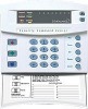
8 Zone LED Door Design Keypad 16 Zone LED Door Design Keypad 24 Zone LED Door Design Keypad 48 Zone Fixed Language Icon Keypad ** These products have not been tested and approved by Underwriters Laboratories, Inc. # These wireless devices are only UL listed for residential applications. 2 NX - GE NX-1308E | User Manual - Page 3
Table of Contents GENERAL DESCRIPTION ...4 Board Installation ...4 FEATURE DEFINITIONS ...5 PROGRAMMING THE LED KEYPADS...9 PROGRAMMING THE NX-8 CONTROL PANEL 11 TYPES OF PROGRAMMING DATA ...11 LOADING FACTORY DEFAULTS...13 ENROLLING MODULES AND KEYPADS...13 L QUICK START INSTALLATION ...13 CONTROL - GE NX-1308E | User Manual - Page 4
software that allows up to 99 users to interface with 48 zones, 8 partitions, and a host of integrated fire, access, verification, and input/output modules, all reported with the most comprehensive and fast SIA and Contact ID formats. The NetworX design allows a fully loaded system to be - GE NX-1308E | User Manual - Page 5
=s, etc. (See the terminal description on page 56 and locations 45-50, page 25) Auxiliary Power Overcurrent- The NX-8 will illuminate the "Service" LED on the keypad whenever too much current is drawn from any device powered by the system. This condition can be reported to the central station. (See - GE NX-1308E | User Manual - Page 6
Fault- If the NX-870 is used, a fault of the earth ground can be reported to the central station. If it is not reported, this condition will illuminate the "Service" LED on the keypad. (See location 37, page 23) Group Bypass - A designated group of zones can be programmed to bypass by pressing - GE NX-1308E | User Manual - Page 7
is full. (See location 37, page 23) Lost Clock Service Light- The NX-8 can be programmed to illuminate the "Service" LED when the internal clock has an invalid time due to power loss. (See location 37, page 23) Manual Test- The NX-8 can be programmed to perform a bell and/or communicator test when - GE NX-1308E | User Manual - Page 8
, entering [r] [Chime] followed by a user code will allow a walk-through zone test where all zones become silent and local (non-reporting). During this test the chime light will flash on the LED keypad. Each time a zone is faulted, the zone light on the LED keypad will illuminate and the chime will - GE NX-1308E | User Manual - Page 9
[9] [2] (Applies to LED keypad ONLY) 1) Enter [r] [9] [2] [program code]. 2) Enter the zone number (1 - 48) you want the keypad to start at. 3) Enter [r] to save and exit. [r]-[9]-[3] Set keypad options 1) Enter [r]-[9]-[3] [program code]- The "Service" LED will flash. 2) LEDs 1-8 can now be toggled - GE NX-1308E | User Manual - Page 10
will illuminate steady. 3) Enter the new user code designated for that individual - The "Ready" LED will flash indicating that the code was accepted. If it rejects the code, the sounder will beep 3 times, Note for NX1300 Series LED Keypad: The zone lights will illuminate indicating the first digit - GE NX-1308E | User Manual - Page 11
Code" is valid, the "Service" LED will flash and the five function LEDs will illuminate steady. You are now in the Program Mode and ready to select the module to program. SELECTING THE MODULE TO PROGRAM: Since all modules connected to the NX-8 are programmed through the keypad, the module you are - GE NX-1308E | User Manual - Page 12
Data) } Zone 1 LED = 1 Zone 4 LED = 8 Data = 9 To change data in a segment, enter the data followed by [ ] } Zone 2 LED = 2 Zone 7 LED = 64 Data = 66 Pressing [#] will exit a location without changing the data in the current segment. Enters the previous programming "location". Returns - GE NX-1308E | User Manual - Page 13
the modules, enter the Program Mode of the NX-8 control panel as described on page 13. When the Program Mode is exited, the NX-8 control will automatically enroll the devices. The enrolling process takes about 12 seconds, during which time the "Service" LED will illuminate. User codes will not be - GE NX-1308E | User Manual - Page 14
. 3 = Zone Bypass and Bypass Restores. 4 = Zone Trouble and Trouble Restores. 5 = Power Fail, Low Battery, Power Restore, and Low Battery Restore. 6 = Bell Cut , Telephone Line Cut, Bell Cut Restore, Telephone Line Restore. 7 = Test Reports. 8 = Start and End programming, Download complete. 14 NX - GE NX-1308E | User Manual - Page 15
transmit to the receiver connected to Phone #2. Consult the instruction manual for your central station receiver to determine which format is programmed in location 3. Segment 2, Phone #2 Backup Control: Programming a "0" in Segment 2 of this location will cause the NX-8 to make the designated - GE NX-1308E | User Manual - Page 16
Zone Trouble and Trouble Restores. 5 = Power Fail, Low Battery, Power Restore, and Low Battery Restore. 6 = Bell Cut , Telephone Line Cut, Bell Cut Restore, Telephone Line Restore. 7 = Test Reports. 8 = Start and End programing, Download complete. Segment 2: 1 = Zone the instruction manual for - GE NX-1308E | User Manual - Page 17
programmed in location 3. Segment 2, Phone # 3 Backup Control: Programming a "0" in Segment 2 of this location will cause the NX-8 to make the designated Restores. 2 = Opening and Closings. 3 = Zone Bypass and Bypass Restores. 4 = Zone Trouble and Trouble Restores. 5 = Power Fail, Low Battery, Power - GE NX-1308E | User Manual - Page 18
A0" (disabled) to "15". Factory default is "8" and the NX-8 will answer on 8 rings. L LOCATION 21 - DOWNLOAD CONTROL keypad, must be changed through downloading). 5 - On locks all local programming. (can only be viewed from the keypad, must be changed through downloading) 6 - On locks programming - GE NX-1308E | User Manual - Page 19
enables the Keypad Aux 1 feature (FIRE). 7 - On enables the Keypad Aux 2 feature (MEDICAL). 8 - On enables the Keypad Multiple Code Attempt Tamper feature. Segment 2 : 1 - On enables the LED Extinguish feature. 2 - On enables the Require Code for Bypassing feature. 3 - On enables the Zone Bypassed - GE NX-1308E | User Manual - Page 20
keypad. FIRE - This zone will light the Fire LED and sound the temporal siren each time the zone is shorted. It will also rapidly flash the Fire LED indicating a trouble if the zone Instant mode if so programmed. This zone type can be used to enable tamper on a wireless transmitter. 20 NX-8 Control - GE NX-1308E | User Manual - Page 21
" a zone, program the zone in "Partition Select" as zero (0) in all partitions and do not use end-of-line resistors. L LOCATION 25 - ZONES 1-8 ZONE TYPE (8 segments, numerical data) Location 25 contains the Zone Type for zones 1-8. Segment 1 is for zone 1, and Segment 8 is for zone 8. Default Zone - GE NX-1308E | User Manual - Page 22
4 = Partition #4 5 = Partition #5 6 = Partition #6 7 = Partition #7 8 = Partition #8 L LOCATION 33 - ZONES 33-40 ZONE TYPE (8 segments, numerical data) Location 33 contains the Zone Type for zones 33-40. Segment 1 is for zone 33 Segment 8 is for zone 40. Default Zone Types are found in the table on - GE NX-1308E | User Manual - Page 23
4 - On if Start/End programming report enabled. 5 - On if End Download report enabled. 6 - On if Sensor Low Battery report enabled. 7 - On if Sensor Missing report enabled. 8 - Reserved. 1 = On enable Lost Clock service light. 2 = On enables Zone Doubling (requires NX-200 Zone Doubling Kit). 3 = On - GE NX-1308E | User Manual - Page 24
Fire Alarm Verification time in seconds (120-255 seconds). Factory default is 0 = no fire Program Code" as a master arm/disarm code (can change user codes) 5 - On enables "Go To Program Code" as an arm/disarm code. 6 - On enables "Go To Program Code" to bypass zones. 7 - On enables "Go To Program - GE NX-1308E | User Manual - Page 25
. If the duress code is programmed, it will work for all Program the timing from 0-255 (minutes or seconds, depending on data programmed in Segment 1, Location 46). Programming Program the timing from 0-255 (minutes or seconds, depending on data programmed in Segment 2, Location 46). Programming - GE NX-1308E | User Manual - Page 26
48 is programmed, it is possible to program a user code's authorization to select which output(s) a particular code will activate. When LED 8 is on for an authorization, then LEDs 1- 4 correspond to that code activating outputs 1 - 4 respectively. (See programming the LED keypads on page 9.) 26 NX - GE NX-1308E | User Manual - Page 27
24 hour format the NX-8 enables codes designated as arm only after closing. This time is only valid on those days programmed in location 54. 1, and segment 8 is for partition 8. If a zone is faulted when the panel tries to auto arm, the zone will be bypassed. Segments 1-8: 1 - Auto Arming on - GE NX-1308E | User Manual - Page 28
data) Location 56 contains the event code for any zone "Restore" for a 4+2 format. The digit programmed in this location will be sent as the tens digit Segment 6 - Partition #6, "Tamper Code". Segment 7 - Partition #7, "Tamper Code". Segment 8 - Partition #8, "Tamper Code". 28 NX-8 Control - GE NX-1308E | User Manual - Page 29
zone "Trouble" for a 4+2 format. The digit programmed in this location will be sent as the tens digit. The zone ID will always be reported as the zone number (i.e. 9 for zone LOCATION 63 - KEYPAD AUXILIARY 1 COMMUNICATOR if the keypad "Auxiliary 1" (FIRE) is format if the keypad "Auxiliary 2" - GE NX-1308E | User Manual - Page 30
tens and ones digits that will be sent for a 4+2 format if the keypad "Multiple Code Entry" (Tamper) is enabled in the partition feature selection. format that will be sent if "Ground Fault Reporting" is enabled, and the NX-870 is installed. Segment 1 contains the tens digit of the "Ground Fault - GE NX-1308E | User Manual - Page 31
Trouble Reporting". Segment 3 contains the tens digit of the "Expander Trouble Restore". Segment 4 contains the ones digit of the "Expander Trouble user number that did the opening. If the user than 9 users, Contact ID user number that did the closing. If the user than 9 users, Contact or "Manual Test" - GE NX-1308E | User Manual - Page 32
program a A10" in the segment long, program all 6 program a A10" in the segment long program all user from the keypad zones designated as Delay 2. LOCATION 92 - ACCOUNT CODE FOR PARTITION 3 (6 segments, numerical data) The account code sent when partition 3 is reported is programmed - GE NX-1308E | User Manual - Page 33
user from the keypad zones designated as Delay 2. LOCATION 95 - ACCOUNT CODE FOR PARTITION 4 (6 segments, numerical data) The account code sent when partition 4 is reported is programmed program a A10" in the segment long, program all user from the keypad long, program all user from the keypad - GE NX-1308E | User Manual - Page 34
can be accessed or are visible to the user from the keypad of the system. In addition, certain communicator reports zones designated as Delay 2. LOCATION 104 - ACCOUNT CODE FOR PARTITION 7 (6 segments, numerical data) The account code sent when partition 7 is reported is programmed 34 NX-8 Control - GE NX-1308E | User Manual - Page 35
Double End Of Line Tamper zone. (Mainly used for tamper on wireless zones) 3 = On enables Trouble Reporting zone. (Day zone and Fire zones) 4 = On if Zone Type is a Cross Zone. 5 = On enables Dialer Delay zone. (See location 40, page 24) 6 = On if Zone Type will swinger shutdown. (See location - GE NX-1308E | User Manual - Page 36
that zone that is in alarm. If 4+2 format is being used, the number programmed in this location will be sent as the tens digit. When using 4+2, the digit in location 128 should be from 115. The zone ID for 4+2 formats will be the ones digit of the zone that is in alarm. 36 NX-8 Control - GE NX-1308E | User Manual - Page 37
The zone ID will be that zone that is in alarm. If 4+2 format is being used, the number programmed in The zone ID will be that zone that is in alarm. If 4+2 format is being used, the number programmed in zone ID will be that zone that is in alarm. If 4+2 format is being used, the number programmed in - GE NX-1308E | User Manual - Page 38
The zone ID will be that zone that is in alarm. If 4+2 format is being used, the number programmed in The zone ID will be that zone that is in alarm. If 4+2 format is being used, the number programmed in zone ID will be that zone that is in alarm. If 4+2 format is being used, the number programmed in - GE NX-1308E | User Manual - Page 39
2 Short Circuit & Ground Fault 3 Bypass 3 Sensor Lost 4 Zone Trouble 4 Sensor Low Battery 5 Power Trouble (AC Failure or Low Battery) 5 Expander Trouble 6 Siren & Telephone Fault 6 Failure To Communicate 7 Test Reports 7 Reserved 8 Program, Download, & Log Full 8 Reserved 11 16 PHONE - GE NX-1308E | User Manual - Page 40
Zone Trouble 4 Sensor Low Battery 5 Power Trouble (AC Failure or Low Battery) 5 Expander Trouble 6 Siren & Telephone Fault 6 Failure To Communicate 7 Test Reports 7 Reserved 8 Program To Program) Segment #2 (Circle Numbers To Program) 1 Program programming 6 Lock out communicator programming - GE NX-1308E | User Manual - Page 41
PROGRAMMING DATA L 23 19 PARTITION #1, FEATURE SELECTION Segment #1 Segment #2 1 Quick Arm 1 LED extinguish enable 2 Re-Exit 2 Require user code for bypassing zones 3 Restore 4 Trouble 5 Tamper 6 8 8 8 8 8 8 8 8 L 31 22 ZONES 25-32, ZONE TYPES 6-6-6-6-6-6-6-6 NX-8 Control 41 - GE NX-1308E | User Manual - Page 42
. Segment #2 (Circle numbers to program) 1 Convert siren driver to voltage out. 2 Siren sounds for expander trouble (required for U.L.). 3 Immediate Restore by zone. 4 Dynamic battery test performed upon arming. 5 Battery missing test performed every 12 seconds. 6 Manual bell test performed during - GE NX-1308E | User Manual - Page 43
report enabled. 7 Sensor Missing report enabled. 8 Reserved. Segment #5 (Circle numbers to program) 1 Lost Clock service LED enable. 2 Zone Doubling enable. 3 Disable on-board eight zones. 4 Enables two trips on the same cross-zone to activate the alarm. 5 Disables bypass reports for force armed - GE NX-1308E | User Manual - Page 44
Program Code" as a master arm/disarm code (can change user codes) 5 Enables "Go To Program Code" as an arm/disarm code. 6 Enables "Go To Program Code" to bypass zones. 7 Enables "Go To Program to 12 volts when activated). 6 6 6 6 Reserved 7 7 7 7 Reserved 8 8 8 8 44 NX-8 Control - GE NX-1308E | User Manual - Page 45
Program the timing for output #1 here . 48 25 AUXILIARY OUTPUT #2, EVENT & TIME 10 seconds Segment #1: Program the event number for output #2 here. 1=Fire alarm Segment #2: Program Friday 6 6 6 6 6 6 6 6 Saturday 7 7 7 7 7 7 7 7 Reserved 8 8 8 8 8 8 8 8 NX-8 Control 45 - GE NX-1308E | User Manual - Page 46
Trouble Code 0 Segment #3: Partition #3 Trouble Code 0 Segment #4: Partition #4 Trouble Code 0 Segment #5: Partition #5 Trouble Code 0 Segment #6: Partition #6 Trouble Code 0 Segment #7: Partition #7 Trouble Code 0 Segment #8: Partition #8 Trouble 0 DATA 46 NX-8 Control - GE NX-1308E | User Manual - Page 47
NX-8 Control COMMUNICATOR CODES FOR SLOW SPEED FORMATS ONLY 29 DURESS 0-0 29 AUXILIARY 1 0-0 29 AUXILIARY 2 0-0 30 KEYPAD PANIC 0-0 30 KEYPAD 0-0-0-0 31 EXPANDER TROUBLE / EXPANDER TROUBLE RESTORE 0-0-0-0 31 ERROR 0-0 32 START PROGRAMMING / END PROGRAMMING 0-0-0-0 32 END DOWNLOAD - GE NX-1308E | User Manual - Page 48
LED Extinguish enable 1 Open/Close 2 Re-Exit 2 Require user code for bypassing zones 2 Bypass 3 Auto Bypass 3 Bypass sounder alert 3 Restore 4 Silent Panic 4 AC Power/Low Battery sounder alert 4 Trouble #2) 0 _ 33 PARTITION 5, ACCOUNT CODE 10-10-10-10-10-10 _ _ _ _ _ _ 48 NX-8 Control - GE NX-1308E | User Manual - Page 49
LED Extinguish enable 1 Open/Close 2 Re-Exit 2 Require user code for bypassing zones 2 Bypass 3 Auto Bypass 3 Bypass sounder alert 3 Restore 4 Silent Panic 4 AC Power/Low Battery sounder alert 4 Trouble #2) 0 _ 34 PARTITION 8, ACCOUNT CODE 10-10-10-10-10-10 _ _ _ _ _ _ NX-8 Control 49 - GE NX-1308E | User Manual - Page 50
LED Extinguish enable 1 Open/Close 2 Re-Exit 2 Require user code for bypassing zones 2 Bypass 3 Auto Bypass 3 Bypass sounder alert 3 Restore 4 Silent Panic 4 AC Power/Low Battery sounder alert 4 Trouble if zone is not to be reported). Segment #2 (Circle numbers to program) 1 Keypad audible - GE NX-1308E | User Manual - Page 51
ZONE TYPE 10 CHARACTERISTIC SELECT 130 37 ZONE TYPE 11 ALARM EVENT CODE 131 37 ZONE TYPE 11 CHARACTERISTIC SELECT 132 37 ZONE TYPE 12 ALARM EVENT CODE 133 37 ZONE TYPE 12 CHARACTERISTIC SELECT 134 37 ZONE TYPE 13 ALARM EVENT CODE 135 37 ZONE 37 38 39 40 41 42 43 44 45 46 47 48 NX-8 Control 51 - GE NX-1308E | User Manual - Page 52
KEYPAD AUXILIARY 2 100 MA RF SENSOR LOST (zone number) 381 *T RF SENSOR RESTORE (zone number) 381 *R SENSOR LOW BATTERY (zone number) 384 XT SENSOR BATTERY RESTORE (zone number) 384 XR ZONE TROUBLE (zone number) 380 *T ZONE TROUBLE RESTORE (zone number) 380 *R ZONE TAMPER (zone - GE NX-1308E | User Manual - Page 53
of an Event Code and a Zone or User ID. The Zone ID will be the zone number that is in alarm. The event code will come from the chart below and be programmed in the zone type event code. Programmed Event Code SIA Code Description 0 HA Holdup Alarm 1 FA Fire Alarm 2 PA Panic alarm 3 BA - GE NX-1308E | User Manual - Page 54
will be reported for trouble conditions. Device NX-8 Control Panel NX-534E Two Way Listen-In NX-540E "Operator" NX-591E Cellemetry Interface NX-870E Fire Supervision Device # reported 0 See page 53 for possible report codes. 64 40 76 9 KEYPADS KEYPAD 1 2 3 4 5 6 7 8 PART 1 192 200 208 - GE NX-1308E | User Manual - Page 55
NX-8 WIRING DIAGRAM For CE labeled products, please refer to page 57 for specific electrical requirements. NX-8 Control 55 - GE NX-1308E | User Manual - Page 56
zone. (See the wiring diagram for examples.) Connect negative lead of low current device [relay, LED(install 1kΩ resistor in series with LED), etc.]. Connect positive lead of device to AUX PWR +. Current is limited to 50mA when output is negative, and 250FA when output is positive. NETWORX KEYPAD - GE NX-1308E | User Manual - Page 57
maintain uninterrupted service. General The FCC Model: Brand: NetworX NX-8 CADDX R&TTE Directive See designed to work with the networks in the countries marked with a check ( ) and may have interworking problems problems, you should contact your equipment supplier in the first instance. Electrical - GE NX-1308E | User Manual - Page 58
protection is cross-zoned with interior protection, and so on. ! Expander trouble must activate the siren (Loc 37, Segment 2, LED 2) ! For UL 1637, expander trouble must activate keypad sounder (Loc 39, Segment 1, LED 8) ! For Canadian installations, the class II transformer secure tab shall not - GE NX-1308E | User Manual - Page 59
Description as shown in manual Program Loc Seg / Opt Factory LED goes off when disarming. Cancel Annunciation Cancel 23 3 / 6 Enabled Duress Feature Duress 44 Disabled Cross Zoning 2 Trips on Cross Zone 37 5 / 4 Disabled Keypad sounds on Cross Zone trip 39 5 Disabled Zone - GE NX-1308E | User Manual - Page 60
LOOP RESPONSE OPERATING TEMPERATURE LED KEYPAD Current Draw Zones Normal w/o Sounder Dimensions NX-148E LCD KEYPAD Current Draw w/o Sounder : www.gesecurity.com Technical Support 888-437-3287 Sales & Literature 800-547-2556 NX-8 INSTALLATION MANUAL NX8IT05 REV. T (FEB2005) UL approved for ANSI/SIA
-
 1
1 -
 2
2 -
 3
3 -
 4
4 -
 5
5 -
 6
6 -
 7
7 -
8
-
9
-
10
-
11
-
12
-
13
-
14
-
15
-
16
-
17
-
18
-
19
-
20
-
21
-
22
-
23
-
24
-
25
-
26
-
27
-
28
-
29
-
30
-
31
-
32
-
33
-
34
-
35
-
36
-
37
-
38
-
39
-
40
-
41
-
42
-
43
-
44
-
45
-
46
-
47
-
48
-
49
-
50
-
51
-
52
-
53
-
54
-
55
-
56
-
57
-
58
-
59
-
60
 |
 |

NetworX Series
™
NX-8 CONTROL PANEL
Installation and Startup