GE P2B940SEJSS Quick Specs - Page 1
GE P2B940SEJSS Manual
 |
View all GE P2B940SEJSS manuals
Add to My Manuals
Save this manual to your list of manuals |
Page 1 highlights
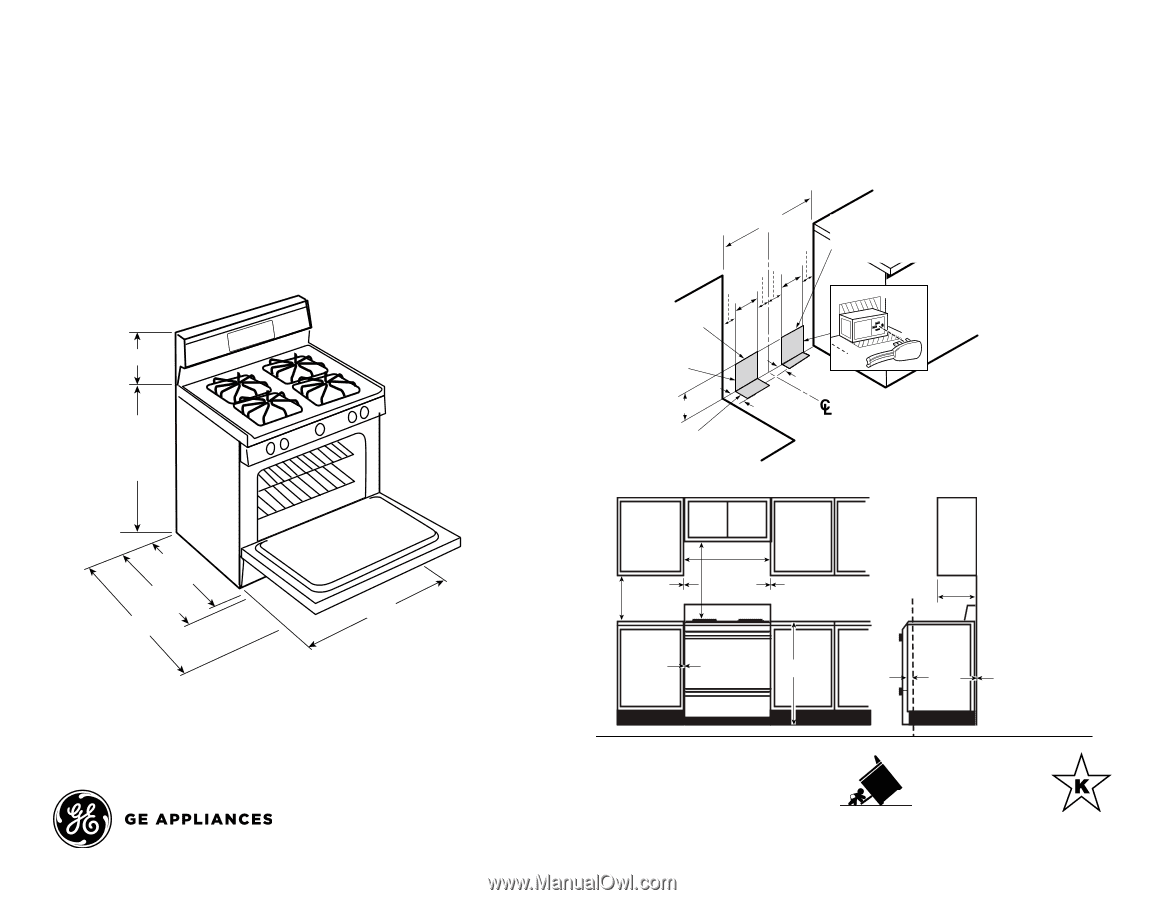
P2B940SEJ GE Profile™ Series 30" Dual-Fuel Free-Standing Convection Range with Warming Drawer SINGLE OVEN GAS RANGE Dimensions and Installation InformatioSnIN(iGnLinEcOheVsE)N GAS RANGE GAS PIPE AND ELECTRICAL GAS PIPE AND ELECTRICAL OUTLET LOCATIONS OUTLET LOCATIONS Electrical Rating: 240V, 60Hz, 5A NOTE: Make gas connections on NOTE: Make gas connections on Installation Inform11a1t/4i"on: Before installing, 11 1/4" consult installation instructions packed with product for current the left side and electrical connections on the right side of the cutout opening. 30 the left side and electrical connections on the right side of the Rceuctoomutmoepnedneidnga. cceptable 30 electrical outlet area. Orient Recommended acc electrical outlet are dimensional data. 36" SINGLE OVEN GAS RANGE 3 the electrical receptacle so the length is parallel to the floor. 36" 4 3 the electrical recep length is parallel to 4 to to 38 GAS PIPE AND3ELE8CTRICAL 36 1/2" 36 1/2" 3 9 Wall-Mounted OUTLE3T 9LOCATIONS Wall-Mounted Recommended area Recommended area fcoorntnhercotuiognh-othfep-iNwpeaOll TE: Make gas connfcoeornctntheirocotuniogsnh-otohfenp-iwpeall 11 1/4" 26 1/4" w/o handle 28 3/4" w/ handle 46 1/4" 26 1/4" w/o handle 30" 28 3/4" w/ handle 46 1/4" stub/shut-off valtvhe.e left side and electrisctuabl/schuot-nonffevaclvtieo. ns This area allowson the ftlousrehairnswtaalllla. tioncutout 30" right side of theThis opening. 2-1/4 flush area allows installation 30 to rear wall. 7-1/2 2 3 Recommended acce e2le-1c/t4rical outlet area the electrical recept 7-1/2 2 length is parallel to 36" Recommended area for 4 to through-the-floor connection of pipe stub/shut-off valve. 3 8 Recommended area for through-the-floor connection 36 1/2" 3 of pipe stub/shut-off valve. 9 Wall-Mounted Recommended area 26 1/4" w/o handle 28 3/4" w/ handle 46 1/4" Minimum to cabinets on either side of the range. 18" 30" 6" Minimum clearance to left wall To cabinets below cooktop and at the range back 30" 30" Minimum 0" Maximumfor through-the-wall connection Minimum todepth for cabinceatbsionents above of pipe either of the sraidcneoguen.tertopss tub3/0s"hut-off valve. 6" Minimum clearance to right wall 18" 6" Minimum clearance to left wall TflhuisM3s1ih0n5i"m"aiunrmesatalalalltoi6ow"nMcsleinaimraunmce to Frotnot edrgee oaf r wall. right wall Maximum depth for cabinets above countertops 15" 2-1/4 the range side panel forward Front edge of 36" from cabinet To c1a/b4in"ets 0" 7-1/2 2the range side panel forward below cooktop and at the range back 0" To cabinets3b6e"low cooktop and at the range back 1/4" Recommended area for through-the-floor connection from cabinet 0" To cabinets below cooktop and at the range back of pipe stub/shut-off valve. For answers to your Monogram,® GE Profile™ MinimuormGtEo® appliance questions, visit our website cabineatst goenappliances.com or call GE Answer Center® either of the sseidrveice, range. 800.626.200300. " 30" Maximum depth for cabinets above countertops All GE ranges are equipped with an Anti-Tip device. The installation of this device is an important, required step in the installation of the range. Specification Created 4/15
-
 1
1 -
 2
2
 |
 |