GE PS968SPSS Quick Specs - Page 1
GE PS968SPSS - Profile - 30" Electric Range Manual
 |
UPC - 084691197546
View all GE PS968SPSS manuals
Add to My Manuals
Save this manual to your list of manuals |
Page 1 highlights
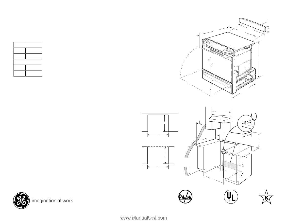
30 PS968SP GE Profile™ 30" Slide-In Electric Range Dimensions and Installation Information (in inches) KW Rating Note: Cabinets installed adjacent to slide-in ranges must have an adhesion spec of at least 194° temperature rating. 240V 12.4 Note: To reduce the possibility of scorching the side walls above the countertop 208V 9.3 when no load is present on burners, it is recommended that a minimum 6" Breaker Size spacing element from adjacent operation. side wall be3al0lo"wSedlifdoer p-ionssEiblleeecx.teRndaendgheigh-heat 240V 40 Amps Receptacle Locations: For all 30" Slide-IAnuRagn.g8e,s 2lo0ca0ll3y a-pkpmroved flexible 208V 40 Amps service cord or conduit must be us3ed0b"eScaliudsee-tienrmEinleacls.aRreannotgaeccessible after range installation. See shaded areaAinudgr.a8w,in2g0fo0r3loc-aktmion of electrical outlet box. Recommended outlet locations allow range to be installed directly against rear wall. Optional Kits For Slide-In 30" SlidBeo-dIny SRiadensge Electric Ranges Dimens(Siolidnes-(ininrainncgheessa)re sold Optional Lower Trim Kits (If counter height is greater (Available At Additional Cost) without sides installed. Can than 36.5", a lower trim kit A(aicJJnAXXuscstSStcttaoa33aeu22cblslthSeWsa)oSedcWsrk(iySngtto(uBaW3aat0inhhrc"dleiekftresgwbe)suahe)-ac-e-4srkn4"dtoa"HusfnHnigrdiiagthinnhisgg3De0im" Senli1JJboeads3XXxrdeieb0oSSpjr-"iaon77inoIgMncds77ssheiyBteWnR(tan.dBisnwtlaWil]des(.nhBiidenKdg(elW)acieoentchnhc[kuneio)etnosenii)tt)tchahaeiabnrsislneoefntt e is recommended to extendIf you are NOT using the the useful height to 38" Filler strip or Backguard: maximum) JXS56WW - White If you are NOT using the MJaXinSt5a6inBB - Black at least 6" from nearest combustible Filler strip or Backguard: 23-3/16 JXS32BB (Black) - 4" High 15" MinR.ear Filler Strips 6 Msuarifnatcaein. at least 6" JXS37WW (White) - 5-1/4" High JXS37CC (Bisque) - 5-1/4" High JXS37BB (Black) - 5-1/4" High W3B00" 7MTin1.0680 - Black Filler Strip Assembly 15" Min. 30 6 4-1/2 from nearest 31-c1o/2mbustible surface. 23-3/16 30 30 6 5 30 4-1/2 31-1/2 If you are using the Filler strip or Backguard: 2-1/46 AEclceecpt5rtiacballe Outlet Area 36 If you are using the Filler strip or Backguard: 25 2-1/4 36 Installation information: B*eWfoalrletoinfrsontat ollfiAnEcglcee,cptcrtiacobanllesult installation instructions packed with product for curcrleosnetdddiomorehnasOniuodtllneetaAlredaata. on model JSP34. GFoEr®aanpspwliaernscteoqyuoeusrtiMonosn,ovg2Ji*scSW8rliao"Ptasom2oleln6utd,/o®mJrdSfGorowSodoEn2eret6lhPsbo/a1rfsno6idt.felielea™t or ge.com or call GE Answer C2eo8nn"mtoenord®meolsJdeSerlPsv3ic4.e, 800.626.2000. JSP26/JSS26/16. Note: Range may be placed 28-1/4* 45-1/8 28-1/4* 45-1/8 with 0" clearance (flush) at 30 30 the back wall and side walls below countertop if the range side trims above the countertop extend beyond the cabinet fronts at least 1/4". (Self-clean models only.) Maintain at least 6" distance from nearest combustible surface. Note: Range may be placed with 0" clearance (flush) at the back wall and side walls below countertop if the range side trims above the countertop extend beyond the cabinet fronts at least 1/4". (Self-clean models only.) Maintain at least 6" distance from nearest combustible surface. 25 30 30 2-7/8" To Front Surface Of Countertop Accessory Backguard 24 30 A/B* 31-1/4 20-5/8" Door Clearance From Front Surface of Countertop 36-1/4 25-3/4** (excluding handle) *JXS37 is 5-1/4" and JX **Total depth from wall t front of closed oven d including handle is 27 Shave Raised Edge To Clear Recommended 30" Min. 31-1/8" Wide Control Panel Excluding Models JSS28 and JSP39 6" Min. FrIafontmdhevWociodauinnlgltsetrhtoepwaarreraanisty.noMtafklaet,seuxrceetshsetwenaslliocnovmeariyngb9,ec/1oaup6nptlieerdtotpo, the glass cooktop causing breakage flooring and cabinets around the range can withstand the heat (up to 200˚F) generated by the range. A. Allow 30" minimum clearance between surface units and bottom of unprotected wood or metal cabinet, folar malelorwetaar2d4a"nmt miniilmlbouamrdwchoe3vne0br"eodMttowimnit.honf owoleosds or metal cabinet is protected by no less then 1/4" than No. 28 MSG sheet metal (.015" thick), .015" thick thick B. sTthaiisnlaepspslisatnecee2l, 3h.0a-23s5/b"1ea6elunmaipnpurmovoerd.0fo2r0A0"E"cclscoepepcapptcertiarnc.bgallteo adjac1e3n"t sMurafaxc.es above the cooktop. However, a is minimum 6" spacing to surfaces lessOthuatnle1t 5A"reabaove recommended to reduce exposure to steam, grease the cooktop splatter and and adjacent cabinetry h1e5at". AMllionw. 1/4" minimum clearance at the back wall. To reduce the risk of burns or fire when reaching over hot surface elements, cabinet storage space above the cooktop be reduced should be avoided. If cabinet storage space is by installing a range hood that projects at least t5o"bbeepy2oro5nvdidtehde above the cooktop, the risk can front of the cabinets. Cabinets installed above the cooktop must be no deeper than 13". 35-7/8"-38" from floor to countertop 2-1/2 7-1/2 2-1/2 30 All GE ranges are equipped with an Anti-Tip device. The installation of this device is an important, required step in the installation of the range. Listed by Underwriters Laboratories 2-7/8" To Front Surface Of Specif2i4cation Created 5/09 31-1/4 30 Accessory Backguard 220447A/B*
-
 1
1 -
 2
2
 |
 |