Gigabyte GA-7TESH2-RH Manual
Gigabyte GA-7TESH2-RH Manual
 |
View all Gigabyte GA-7TESH2-RH manuals
Add to My Manuals
Save this manual to your list of manuals |
Gigabyte GA-7TESH2-RH manual content summary:
- Gigabyte GA-7TESH2-RH | Manual - Page 1
GA-7TESH2-RH Dual Xeon Processor Motherboard USER'S Manual Xeon® Processor Motherboard Rev. 1001 * The WEEE marking on the product indicates this product must not be disposed of with user's other household waste and - Gigabyte GA-7TESH2-RH | Manual - Page 2
Table of Contents Table of Content Item Checklist 4 Chapter 1Introduction 5 1.1.Considerations Prior to Installation 5 1.2.Features Summary 6 1.3.GA-7TESH1-RH Motherboard Component 8 Chapter 2Hardware Installation Process 11 2.1.Installing Processor and CPU Haet Sink 11 2.1.1.Installing CPU - Gigabyte GA-7TESH2-RH | Manual - Page 3
English GA-7TESH2-RH Motherboard System Management ...65 Console Redirection ...67 Boot ...69 Exit ...70 3 - Gigabyte GA-7TESH2-RH | Manual - Page 4
Item Checklist The GA-7TESH2-RH motherboard Serial ATA cable x 6 I/O Shield Kit CD for motherboard driver & utility GA-7TESH2-RH quick reference guide Introduction * The items listed above are for reference only, and are subject to change without notice. 4 - Gigabyte GA-7TESH2-RH | Manual - Page 5
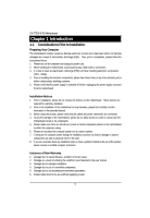
GA-7TESH2-RH installation, please follow the instructions below: 1. Please turn off the information in the provided manual. 3. Before using the about any installation steps or have a problem related to the use of the product, the conditions recommended in the user manual. 3. Damage due to improper - Gigabyte GA-7TESH2-RH | Manual - Page 6
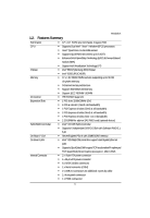
On-Board VGA On-Board LAN Internal Connector 12" x 13" EATX size form factor, 8 layers PCB Supports Dual Intel® Xeon® Nehalem-EP 2S processors Xeon® Quad Core in LGA 1366 socket Supports QuickPath Interconnect up to 6.4GT/s Enhanced Intel SpeedStep Technology (EIST) & Demand Based Switch - Gigabyte GA-7TESH2-RH | Manual - Page 7
English GA-7TESH2-RH Motherboard Rear Panel I/O Hardware Monitor BIOS Additional Features 6 System Voltage Detect Support basic ASF remote transaction through CSA Bus with hardware circuit Phoenix BIOS on 16Mb flash RAM Supports S4, S5 - Gigabyte GA-7TESH2-RH | Manual - Page 8
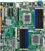
. 13. 14. 15. 16. 17. 18. 19. 20. 21. 22. 23. 24. 25. 26. 27. 28. 29. 30. 31. 32. 33. 34. 35. 36. 37. GA-7TESH2-RH Motherboard Component Code Description CPU1 Primary CPU CPU2 Secondary CPU U82 Intel Tylersburg-36D IOH U60 Intel ICH10R U188 Winbond W83792G U6 Intel 82576EB GbE - Gigabyte GA-7TESH2-RH | Manual - Page 9
English GA-7TESH2-RH Motherboard No Code Description 38. PCI-E1 39. DIMMC1 40. DIMMC2 41. DIMMB1 42. DIMMB2 43. DIMMA1 44. DIMMA2 45. DIMMD2 46. DIMMD1 47. DIMME2 - Gigabyte GA-7TESH2-RH | Manual - Page 10
English GA-7TESH2-RH Motherboard 19 70 11 68 10 9 8 13 67 69 17 12 34 35 36 37 57 18 25 24 23 64 662566 63 4 22 61 21 20 16 14 56 55 6 27 5 2 38 3940 41424344 7 54 53 52 51 32 33 59 58 45 46 47484950 3 15 31 30 1 26 29 28 60 10 - Gigabyte GA-7TESH2-RH | Manual - Page 11
socket. 3. Apply thermal grease on the processor before placing cooling fan. 4. Please make sure the CPU type is supported by the motherboard. 5. If you do not match the CPU socket Pin 1 and CPU cut edge well, it please replace the metal cover and push the metal lever back into locked position. 11 - Gigabyte GA-7TESH2-RH | Manual - Page 12
English GA-7TESH2-RH Motherboard 2.1.2. Installing Heat Sink Step 1 Attach the heat sink clip to the processor socket. Step 2 Secure the cooing fan with screws. Step 3 Connect processor fan can cable to the processor fanconnector 2 2 2 1 12 - Gigabyte GA-7TESH2-RH | Manual - Page 13
module can be installed in only one direction. If you are unable to insert the module, please switch the direction. The motherboard supports DDR3 memory modules, whereby BIOS will automatically detect memory capacity and specifications. Memory modules are designed so that they can be inserted only - Gigabyte GA-7TESH2-RH | Manual - Page 14
Hardware Installation Process Installation Steps: Step 1. Insert the DIMM memory module vertically into the DIMM slot, and push it down. Step 2. Close the plastic clip at both edges of the DIMM slots to lock the DIMM module. NOTE! DIMM must be populated in order starting from DIMMA1/D1 socket. For - Gigabyte GA-7TESH2-RH | Manual - Page 15
English GA-7TESH2-RH Motherboard U-DIMM Population Table Interleave Channel A Channel B Channel C mode DIMMA1/D1 DIMMA2/D2 DIMMB1/E1 DIMMB2/E2 DIMMC1/F1 DIMMC2/F2 Total Memory Single Channel - Gigabyte GA-7TESH2-RH | Manual - Page 16
English GA-7TESH2-RH Motherboard R-DIMM Population Table Interleave Channel A Channel B Channel C mode DIMMA1/D1 DIMMA2/D2 DIMMB1/E1 DIMMB2/E2 DIMMC1/F1 DIMMC2/F2 Total Memory Single Channel - Gigabyte GA-7TESH2-RH | Manual - Page 17
Hardware Installation Process 2.3. Connect ribbon cables, cabinet wires, and power supply 2.3.1. I/O Back Panel Introduction 17 - Gigabyte GA-7TESH2-RH | Manual - Page 18
English GA-7TESH2-RH Motherboard PS/2 Keyboard and PS/2 Mouse Connector To install a PS/2 , speaker...etc. have a standard USB interface. Also make sure your OS supports USB controller. If your OS does not support USB controller, please contact OS vendor for possible patch or driver updated. For - Gigabyte GA-7TESH2-RH | Manual - Page 19
LAN LED Description LED2 (Green/Yellow) Hardware Installation Process LED1 (Green) Name LED1 LED2 Color Green Green Green Green Green Yellow Yellow Condition ON BLINK OFF OFF BLINK ON BLINK ON BLINK Description LAN Link / no Access LAN Access Idle 10Mbps connection Port identification with 10 - Gigabyte GA-7TESH2-RH | Manual - Page 20
English GA-7TESH2-RH Motherboard 2.4. Connectors Introduction 4 6 25 15 7 24 17 13 12 11 10 9 8 27 26 14 22 23 3 1 5 21 18 16 19 2 20 1. ATX 2. 12V_AUX1 3. 12V_AUX2 4. COMB 5. - Gigabyte GA-7TESH2-RH | Manual - Page 21
English GA-7TESH2-RH Motherboard 1/2/3 ) ATX/12V_AUX1/12V_AUX2 (24-pin/8-pin ATX not connected, the system will not start. Caution! Please use a power supply that is able to support the system voltage requirements. It is recommended that a power supply that can withstand high power consumption be - Gigabyte GA-7TESH2-RH | Manual - Page 22
13 1 12 24 Connector Introduction Pin No. 1 2 3 4 5 6 7 8 9 10 11 12 Definition 3.3V 3.3V GND +5V GND +5V GND Power Good 5V SB(stand by +5V) +12V +12V(Only for 24-pin ATX) 3.3V(Only for 24-pin ATX) Pin No. 13 14 15 16 17 18 19 20 21 22 23 24 Definition 3.3V -12V GND PS_ON(soft On/Off) GND GND - Gigabyte GA-7TESH2-RH | Manual - Page 23
English GA-7TESH2-RH Motherboard 4 ) COMB 21 10 9 Pin No. 1 2 3 4 5 6 7 8 9 10 Definition DCDSIN2 SOUT2 DTR2GND DSR2RTS2CTS2RI2NC 5/6 ) USB1/2 (USB cable connectors) Be careful with the polarity of the front USB - Gigabyte GA-7TESH2-RH | Manual - Page 24
7 ) F_PANEL (2X12 Pins Front Panel connector) Connector Introduction Please connect the power LED, PC speaker, reset switch and power switch of your chassis front panel to the F_PANEL connector according to the pin assignment above. 12 23 24 Pin No. 1. 2. 3. 4. 5. 6. 7. 8. 9. 10. 11. 12. 13. 14 - Gigabyte GA-7TESH2-RH | Manual - Page 25
Connector Introduction 8/9/10/11/12/13 ) SATA 0~5 (Serial ATA cable connectors) SATA 3Gb/s can provide up to 300MB/s stransfer rate. Please refer to the BIOS setting for the SATA 3Gb/s and install the proper driver in order to work properly. 7 Pin No. Definition 1 GND 2 TXP 3 TXN 4 GND 5 - Gigabyte GA-7TESH2-RH | Manual - Page 26
English GA-7TESH2-RH Motherboard 15 manufacturer. Dispose of used batteries according to the manufacturer's instructions. 16~23 ) CPU_FAN1/2 / SYS_FAN1/2/3/4/5/6 (CPU fan power connector wires. A red power connector wire indicates a positive connection and requires a +12V power voltage. The black - Gigabyte GA-7TESH2-RH | Manual - Page 27
24 ) IPMB1 (IPMB Type A connector) Connector Introduction 1 Pin No. Definition 1 IPMB_SMBCLK 2 GND 3 IPMB_SMBDAT 25 ) IPMB2 (IPMB Type B connector) 1 Pin No. Definition 1 IPMB_SMBCLK 2 GND 3 IPMB_SMBDAT 4 NC 27 - Gigabyte GA-7TESH2-RH | Manual - Page 28
English GA-7TESH2-RH Motherboard 26 ) SGPIO_JP1 (ICH10 SGPIO connector) SGPIO is stands for Serial General Purpose Input/Output which is a 4-signal (or 4-wire) bus used between a Host Bus - Gigabyte GA-7TESH2-RH | Manual - Page 29
2.5. Jumper Setting 6 7 5 8 2 34 1 Jumper Setting 29 - Gigabyte GA-7TESH2-RH | Manual - Page 30
English GA-7TESH2-RH Motherboard 1 ) CLR_CMOS (Clear CMOS jumper) You may clear the CMOS data to its default values by this jumper. Default value doesn't include the "Shunter" to - Gigabyte GA-7TESH2-RH | Manual - Page 31
English GA-7TESH2-RH Motherboard 7/8 ) JP_STRAP2/ JP_STRAP8 (PilotII firmware upgrade jumper) JP_STRAP2 1 1 1 1 JP_STRAP8 1 1 1 1 Descripeion Boot from BMC BOOT SPI Interface. (Default setting) Boot From BMC LPC BOOT ROM interface. - Gigabyte GA-7TESH2-RH | Manual - Page 32
GA-7TESH2-RH Motherboard BIOS Setup BIOS (Basic Input and Output System) includes a CMOS SETUP utility which allows user to configure required settings or to activate certain system - Gigabyte GA-7TESH2-RH | Manual - Page 33
BIOS Setup GETTINGHELP Main Menu The on-line description of the highlighted setup function is displayed at the bottom of the screen. Status Page Setup Menu / Option Page Setup Menu Press F1 to pop up a small help window that describes the appropriate keys to use and the possible selections for the - Gigabyte GA-7TESH2-RH | Manual - Page 34
GA-7TESH2-RH Motherboard Main Once you enter Phoenix BIOS Setup Utility, the Main Menu (Figure 1) will appear on the screen. Use arrow keys to select among the - Gigabyte GA-7TESH2-RH | Manual - Page 35
BIOS Setup Advanced About This Section: Advanced With this section, allowing user to configure your system for advanced operation. User can set the Processor configuration, Memory configuration, Advanced chipset control, PCI configuration , SATA configuration, I/O Device configuration, Boot - Gigabyte GA-7TESH2-RH | Manual - Page 36
GA-7TESH2-RH Motherboard Processor Configuration 36 - Gigabyte GA-7TESH2-RH | Manual - Page 37
multiprocessor(MP) specification revision level. Some operating system will require 1.1 for compatibility reasons. 1.4 Support MPS Version 1.4 . (Default setting) 1.1 Support M PS Version 1.1. Intel (R) Virtualization Technology Intel(R) Virtualization Technology will allow a platform to run - Gigabyte GA-7TESH2-RH | Manual - Page 38
GA-7TESH2-RH Motherboard Enabled Enable Intel Virtualization Technology. (Default setting) Disabled Disable this function. Execute Disable Bit Enabled Enable Execute Disable Bit. (Default setting) Disabled Disable this - Gigabyte GA-7TESH2-RH | Manual - Page 39
Threading Technology. (Default setting) Disabled Disable Intel Hyper Threading Technology. A20M Support Enabled Enable A20M Support. (Default setting) Disabled Disable A20M Support. Machine Checking Enabled Enable Machine Checking. (Default setting) Disabled Disable Machine Checking - Gigabyte GA-7TESH2-RH | Manual - Page 40
GA-7TESH2-RH Motherboard Power Management Figure 2-1-1: Power Management EIST (GV3) & C State Enabled Enable EIST (GV3) and C State items. (Default setting) Disabled Disable EIST (GV3) and C State items. - Gigabyte GA-7TESH2-RH | Manual - Page 41
SW_ALL BIOS Setup In SW_ALL mode, the OS Power Manager is responsible for coordinating the P-state among loical processors with dependencies and must initiate the transition on all of those Logical Processors. SW_ANY In SW_ANY mode, the OS Power Manager is responsible for corrdinating the P-state - Gigabyte GA-7TESH2-RH | Manual - Page 42
GA-7TESH2-RH Motherboard state. (Default setting) Disabled Disable CPU C6 Report. CPU C7 Report Enabled Desire state for the Nehalem core C7 state include in the CST - Gigabyte GA-7TESH2-RH | Manual - Page 43
Memory Configuration BIOS Setup 43 - Gigabyte GA-7TESH2-RH | Manual - Page 44
GA-7TESH2-RH Motherboard Base Memory/Extended Memory/DIMM Status These category is display- set to 'No' automatically. No No chnages. (Default setting) Memory Control Settings Manual Auto Select 'Manual" will pops up sub-menu for configuration. Auto configuration. (Default setting) Memory RAS - Gigabyte GA-7TESH2-RH | Manual - Page 45
GA-7TESH2-RH Motherboard Advanced Chipset Configuration Figure 2-3: Advanced Chipset Configuration 45 - Gigabyte GA-7TESH2-RH | Manual - Page 46
BIOS Setup Figure 2-3-1: Intel VT for Directed I/O (VT-d) 46 - Gigabyte GA-7TESH2-RH | Manual - Page 47
GA-7TESH2-RH Motherboard Intel VT for Directed I/O (VT-d) Interrupt Remapping Enabled Enable Interrupt Remapping. (Default setting) Disabled Disable Interrupt Remapping. Coherency Support Enabled Enable Coherency Support. Disabled Disable Coherency Support. (Default setting) ATS Enabled - Gigabyte GA-7TESH2-RH | Manual - Page 48
value of QPI frequency. Option available: Auto, 4.800GT, 5.866GT. Default setting is Auto. QPI DCA Support Enabled Enable QPI DCA Support. (Default setting) Disabled Disable QPI DCA Support. QPI Error Report Enabled Enable QPI Error Report. Disabled Disable QPI Error Report. (Default setting - Gigabyte GA-7TESH2-RH | Manual - Page 49
GA-7TESH2-RH Motherboard PCI Configuration Figure 2-4: PCI Configuration PCI Slot 1/2/3/4/5 Option ROM Enabled Enable this item to initialize device expansion ROM. (Defualt setting) Disabled Disable this function. - Gigabyte GA-7TESH2-RH | Manual - Page 50
ROM Scan Enabled Enable onboard LAN2 device and initialize device expansion ROM. (Default setting) Disabled Disable this function. Legacy USB Support This option allows user to function support for legacy USB. Enabled Enables support for legacy USB (Default setting) Disabled Disables - Gigabyte GA-7TESH2-RH | Manual - Page 51
GA-7TESH2-RH Motherboard SATA Configuration Figure 2-5: SATA Configuration Serial ATA Enabled Disabled Enables on-board serial ATA function. (Default setting) Disables on-board serial ATA function. Native - Gigabyte GA-7TESH2-RH | Manual - Page 52
Disable this function. (Default setting) SATA AHCI Enable Enabled Set this item to enable SATA AHCI function for WinXP-SP1+IAA driver supports AHCI mode. Disabled Disabled this function. (Default setting) SATA Port 1/2/3/4/5/6 The category identifies the types of Serial SATA hard disk from - Gigabyte GA-7TESH2-RH | Manual - Page 53
GA-7TESH2-RH Motherboard LBA Mode 32-Bit I/O Transfer Mode This field shows if the device type in the specific IDE channel support LBA Mode. Enable this function to max imize the IDE data transfer rate. This field shows the information of Teansfer Mode. Ultra DMA Mode This - Gigabyte GA-7TESH2-RH | Manual - Page 54
I/O DeviceConfiguration BIOS Setup Figure 2-6: I/O Device Configuration Serial Port A This allows users to configure serial prot A by using this option. Enabled Disabled Enable the configuration. (Default setting) Disable the configuration. Base I/O Address/IRQ 3F8/IRQ4 Set IO address to 3F8/ - Gigabyte GA-7TESH2-RH | Manual - Page 55
GA-7TESH2-RH Motherboard Base I/O Address/IRQ 3F8/IRQ4 Set IO address to 3F8/IRQ4. 2F8/IRQ3 Set IO address to 2F8/IRQ3. (Default setting) 3E8/IRQ7 Set IO address to 3E8/IRQ7. 2E8/IRQ35 Set IO address to 2E8/IRQ5. 55 - Gigabyte GA-7TESH2-RH | Manual - Page 56
Boot DeviceConfiguration BIOS Setup Figure 2-7: Boot Configuration Boot -time Diagnostic When this item is enabled, system will shows Diagnostic status when system boot. Enabled Enable Boot-time Diagnostic. (Default setting) Disabled Disable this function. Post Error Pause The category - Gigabyte GA-7TESH2-RH | Manual - Page 57
GA-7TESH2-RH Motherboard NumLock This option allows user to select power-on state for NumLock. On Enable NumLock. (Default setting) Off Disable this function. 57 - Gigabyte GA-7TESH2-RH | Manual - Page 58
GA-7TESH2-RH Motherboard Thermal and Acoustic Configuration Figure 2-8: Thermal and Acoustic Configuration Open loop Thermal Throttle Enabled Open loop Thermal Throttle. (Default setting) Disabled Disable Open loop - Gigabyte GA-7TESH2-RH | Manual - Page 59
GA-7TESH2-RH Motherboard Close loop Thermal Throttle Enabled Close loop Thermal Throttle. (Default setting) Disabled Disable Close loop Thermal Throttle. Temperature Hysteresis This item is user defined. - Gigabyte GA-7TESH2-RH | Manual - Page 60
GA-7TESH2-RH Motherboard Power Figure 3: Power Power On by RTC Alarm You can set (Default setting) Off Disable this function. If Resume On Time is set to On status: RTC Alarm control select: Manual/Auto Time (0~23) : (0~59) : (0~59) Power On PCI & PCIE Devices Enabled Enable Power On PCI & - Gigabyte GA-7TESH2-RH | Manual - Page 61
BIOS Setup After Power Failure This option provides user to set the mode of operation if an AC / power loss occurs. Power On System power state when AC cord is re-plugged. Stay Off Last State Do not power on system when AC power is back. Set system to the last sate when AC power is removed. Do - Gigabyte GA-7TESH2-RH | Manual - Page 62
GA-7TESH2-RH Motherboard Security About This Section: Security In this section, user can set either supervisor or user passwords, or both for different level of password securities. - Gigabyte GA-7TESH2-RH | Manual - Page 63
BIOS Setup Set User Password You can only enter but do not have the right to change the options of the setup menus. When you select this function, the following message will appear at the center of the screen to assist you in creating a password. Type the password up to 6 characters in lengh and - Gigabyte GA-7TESH2-RH | Manual - Page 64
GA-7TESH2-RH Motherboard Server Figure 5: Server 64 - Gigabyte GA-7TESH2-RH | Manual - Page 65
System Management BIOS Setup 65 - Gigabyte GA-7TESH2-RH | Manual - Page 66
GA-7TESH2-RH Motherboard Server Management This category allows user to view the server management features. Including information of Motherboard Hardware information and software information. BMC IP Address - Gigabyte GA-7TESH2-RH | Manual - Page 67
B as the COM port address. Disabled Disable this function. (Default setting) Flow Control This option provide user to enable the flow control function. None Not supported. XON/OFF Software control. CTS/RTS Hardware control. (Default setting) Baud Rate 67 - Gigabyte GA-7TESH2-RH | Manual - Page 68
GA-7TESH2-RH Motherboard This option allows user to set the specified baud rate. Options 300, 1200, 2400, 9600, 19.2K, 38.4K, 57.6K, 115.2K. Terminal - Gigabyte GA-7TESH2-RH | Manual - Page 69
Boot BIOS Setup Figure 6: Boot Boot Priority Order This field determines which type of device the system attempt to boot from after PhoenixBIOS Post completed. Specifies the boot sequence from the available devices. If the first device is not a bootable device, the system will seek for next - Gigabyte GA-7TESH2-RH | Manual - Page 70
GA-7TESH2-RH Motherboard Exit Figure 7: Exit About This Section: Exit Once you have changed all of the set values in the BIOS setup, you should save your - Gigabyte GA-7TESH2-RH | Manual - Page 71
BIOS Setup Exit Saving Changes This option allows user to exit system setup with saving the changes. Press on this item to ask for the following confirmation message: Pressing 'Y' to store all the present setting values tha user made in this time into CMOS. Therefore, whenyou boot up your - Gigabyte GA-7TESH2-RH | Manual - Page 72
GA-7TESH2-RH Motherboard Exit Discarding Changes This option allows user to exit system setup without changing anyprevious settings values in CMOS. The previous selection remain in effect. This will exit the Setup Utility and restart your compuetr when selecting this option. 72 - Gigabyte GA-7TESH2-RH | Manual - Page 73
BIOS Setup Load Settup Default This option allows user to load default values for all setup items. When you press on this item, you will get a confirmation dialog box with a message as below: 73 - Gigabyte GA-7TESH2-RH | Manual - Page 74
GA-7TESH2-RH Motherboard Discard Changes This option allows user to load previos values from CMOS for all setup item. When you press on this item, you will get a confirmation dialog box with a message as below: 74 - Gigabyte GA-7TESH2-RH | Manual - Page 75
BIOS Setup Save Changes This option allows user to save setup dat ato CMOS. When you press on this item, you will get a confirmation dialog box with a message as below: Press [Yes] to save setup data to CMOS. 75
-
 1
1 -
 2
2 -
 3
3 -
 4
4 -
 5
5 -
 6
6 -
 7
7 -
8
-
9
-
10
-
11
-
12
-
13
-
14
-
15
-
16
-
17
-
18
-
19
-
20
-
21
-
22
-
23
-
24
-
25
-
26
-
27
-
28
-
29
-
30
-
31
-
32
-
33
-
34
-
35
-
36
-
37
-
38
-
39
-
40
-
41
-
42
-
43
-
44
-
45
-
46
-
47
-
48
-
49
-
50
-
51
-
52
-
53
-
54
-
55
-
56
-
57
-
58
-
59
-
60
-
61
-
62
-
63
-
64
-
65
-
66
-
67
-
68
-
69
-
70
-
71
-
72
-
73
-
74
-
75
 |
 |

USER’S Manual
GA-7TESH2-RH
Dual Xeon Processor Motherboard
Xeon
®
Processor Motherboard
Rev. 1001
*
The WEEE marking on the product indicates this product must not be disposed of with
user's other household waste and must be handed over to a designated collection point
for the recycling of waste electrical and electronic equipment!!
*
The WEEE marking applies only in European Union's member states.