Gigabyte GA-8I865GVMK Manual
Gigabyte GA-8I865GVMK Manual
 |
View all Gigabyte GA-8I865GVMK manuals
Add to My Manuals
Save this manual to your list of manuals |
Gigabyte GA-8I865GVMK manual content summary:
- Gigabyte GA-8I865GVMK | Manual - Page 1
but they support 2X(3.3V) only. The GA-8I865GVMK (or any AGP 4X/8X only) motherboards might not function properly, If you install this card in it. Note : Although Gigabyte's AG32S(G) graphics card is based on ATi Rage 128 Pro chip, the design of AG32S(G) is compliance with AGP 4X(1.5V) specification - Gigabyte GA-8I865GVMK | Manual - Page 2
herein. Third-party brands and names are the property of their respective owners. Please do not remove any labels on motherboard, this may void the warranty of this motherboard. Due to rapid change in technology, some of the specifications might be out of date before publication of this booklet. - Gigabyte GA-8I865GVMK | Manual - Page 3
to w hich it refers) Mother Boa rd GA-8I865GVMK is in conformity with (reference to the specification under which conformity is declared) in accordance with 89 systems; Equi pment for receivi ng and/or distribution fr om sound and television signals o ENV 55104 o EN50091-2 lmmuni ty requireme - Gigabyte GA-8I865GVMK | Manual - Page 4
CA 91748 Phone/FaxNo: (818) 854-9338/ (818) 854-9339 hereby declares that the product Product Name: Motherboard Model Number: GA-8I865GVMK Conforms to the following specifications: FCC Part 15, Subpart B, Section 15.107(a) and Section 15.109(a), Class B Digital Device Supplementary Information: This - Gigabyte GA-8I865GVMK | Manual - Page 5
GA-8I865GVMK P4 Titan Series Motherboard USER'S MANUAL Pentium® 4ProcessorMotherboard Rev. 1003 12ME-8I865GV-1003 - Gigabyte GA-8I865GVMK | Manual - Page 6
Warning 4 Chapter 1 Introduction 5 Features Summary 5 GA-8I865GVMK Motherboard Layout 7 Block Diagram 8 Chapter 2 Hardware Installation Process 11 Step 1: Install the Central Processing Unit (CPU 12 Step 1-1: CPU Installation 12 Step 1-2: CPU Cooling Fan Installation 13 Step 2: Install - Gigabyte GA-8I865GVMK | Manual - Page 7
56 Exit Without Saving 57 Chapter 4 Technical Reference 59 @BIOS™ Introduction 59 EasyTune™ 4 Introduction 60 Flash BIOS Method Introduction 61 Method 1 : Q-Flash 61 Method 2 : @BIOS Utility 74 2- / 4- / 6-Channel Audio Function Introduction 76 Jack-Sensing Introduction 82 Xpress Recovery - Gigabyte GA-8I865GVMK | Manual - Page 8
screw from the motherboard PCB surface, because the circuit wire may be near by the hole. Be careful, don't let the screw contactany printed circuit write or parts on the PCB thatare near the fixing hole, otherwise it maydamage the board orcause board malfunctioning. GA-8I865GVMK Motherboard - 4 - - Gigabyte GA-8I865GVMK | Manual - Page 9
® Pentium® 4 800/533/400MHz FSB - 2nd cache depends on CPU - Intel® Chipset 865GV HOST/AGP/Controller - Intel® ICH5 I/O Controller Hub - 4 184-pin DDR DIMM sockets - Supports DualChannel DDR400/DDR333/DDR266 DIMM - Supports 128MB/256MB/512MB/1GBunbuffered DRAM - Supports up to 4GB DRAM (Max) (Note - Gigabyte GA-8I865GVMK | Manual - Page 10
specific bus frequencies are not the standard specifications for CPU, chipset and most of the peripherals. Whether your system can run under these specific bus frequencies properly will depend on your hardware configurations, including CPU, Chipsets, Memory, Cards... etc. GA-8I865GVMK Motherboard - Gigabyte GA-8I865GVMK | Manual - Page 11
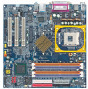
English GA-8I865GVMK Motherboard Layout VGA COMA KB_MS R_U SB SOC KET 478 RAM_LED C PU_FAN ATX FDD LPT GA-8I865GVMK DDR1 DDR2 DDR3 DDR4 IDE2 IDE1 USB AUDIO1 LAN A TX_12V I ntel 8256 2E Z C OM B I TE 8712 CD_I N SU R_C EN C ODEC F_AU DIO GAME I R_CI R I ntel 865GV BAT PCI1 SYS - Gigabyte GA-8I865GVMK | Manual - Page 12
Socket 478 CPU CPUCLK+/- (100/133/200MHz) System Bus 800/533/400M Hz 266/333/400M Hz Intel 82562EZ Intel 865GV DDR RAM MCHCLK (100/133/200MHz) 66 MHz 33 MHz 48 MHz 14.318 MHz BIOS Intel LPC /133/200MHz) AGPCLK (66MHz) MCHCLK (100/133/200mHz) ICH3V66 (66MHz) GA-8I865GVMK Motherboard - 8 - - Gigabyte GA-8I865GVMK | Manual - Page 13
- 9 - Introduction English - Gigabyte GA-8I865GVMK | Manual - Page 14
English GA-8I865GVMK Motherboard - 10 - - Gigabyte GA-8I865GVMK | Manual - Page 15
, you must complete the following steps: Step 1- Install the Central Processing Unit (CPU) Step 2- Install memory modules Step 3- Install expansion cards Step 4- Connect ribbon cables power cable to the power outlet. Continue with the BIOS/software installation. - 11 - Hardware Installation Process - Gigabyte GA-8I865GVMK | Manual - Page 16
CPU type is supported by the motherboard. 2. If you do not match the CPU socket Pin 1 and CPU cut edge well, it will cause improper installation. Please change the insert orientation. Step 1-1: CPU Pin1 indicator 3. CPU Top View GA-8I865GVMK Motherboard 4. Locate Pin 1 in the socket and - Gigabyte GA-8I865GVMK | Manual - Page 17
fan, you might pull the processor out of the CPU socket alone with the cooling fan, and might damage CPU cooling fan user's manual for more detail installation procedure. 1. Fasten the cooling fan supportingbase onto the CPU socket on the motherboard. 2. Make sure the CPU fan is plugged to the CPU - Gigabyte GA-8I865GVMK | Manual - Page 18
Please change the insert orientation. The motherboard has 4 dual inline memory module (DIMM) sockets. The BIOS will automatically dete cts me mory mem ory module vertically into the DIMM socket. Then push it down. GA-8I865GVMK Motherboard 3. Close the plastic clip at both edges of the DIMM sockets - Gigabyte GA-8I865GVMK | Manual - Page 19
building high performance and lowlatency DRAM subsystem thatare suitable for servers, workstations, and full range of desktop PCs. Dual Channel DDR: GA-8I865GVMK supports Dual Channel Technology. When Dual Channel Technology is activated, the bandwidth of mem ory bus will be double the original one - Gigabyte GA-8I865GVMK | Manual - Page 20
X Step 3: Install expansion cards 1. Read the related expansion card's instruction document before install the expansion card into the computer. 2. Remove your , setup BIOS utility of expansion card from BIOS. 8. Install related driver from the operating system. GA-8I865GVMK Motherboard - 16 - Gigabyte GA-8I865GVMK | Manual - Page 21
) This conne ctor supports stan dard PS/2 keyboard and PS/2 mouse. PS/2 Keyboard Connector (6pin Female) v/x USB/LAN Connector USB 0 USB 1 LAN USB 2 USB 3 controller, please contact OS vendor for p ossible patch or driver upgrade.Formoreinformation pleasecontactyour OS or device(s) vendors. - 17 - Gigabyte GA-8I865GVMK | Manual - Page 22
Port (25 pin Female) This connector supports 1 standard COM port , 1 Parallelportand Audio Connectors Line In (Rear Speaker) Line Out(FrontSpeaker) MIC In (Center and Subwoofer) After install onboard audio driver audio setup installation, please refer to page 76. GA-8I865GVMK Motherboard - 18 - - Gigabyte GA-8I865GVMK | Manual - Page 23
English Step 4-2: Connectors Introduction 1 3 11 2 5 6 16 8 13 4 14 20 7 12 18 17 19 15 10 9 1) ATX_12V 2) ATX 3) CPU_FAN 4) SYS_FAN 5) FDD 6) IDE1 / IDE2 7) SATA0 / SATA1 8) BAT 9) F_PANEL 10) PWR_LED 11) RAM_LED 12) F_AUDIO 13) CD_IN 14) SUR_CEN 15) F_USB1 / F_USB2 16) COMB 17) - Gigabyte GA-8I865GVMK | Manual - Page 24
English 1) ATX_12V (+12V Power Connector) This connector (ATX_12V) supplies the CPU operation voltage (Vcore). If this "ATX_12V connector" is not connected, system cannot boot. Pin No. Definition 2 1 1 GND 15 GND 16 GND 17 GND 18 -5V 19 VCC 20 VCC GA-8I865GVMK Motherboard - 20 - - Gigabyte GA-8I865GVMK | Manual - Page 25
Fan Connector) Please note, a proper installation of the CPU cooler is essential to prevent the CPU from running under abnormal condition or damaged by overheating. The CPU fan connector supports Max. current up to 600 m A. 1 Pin No. Definition 1 GND 2 +12V 3 Sense 4) SYS_FAN (System Fan - Gigabyte GA-8I865GVMK | Manual - Page 26
English 5) FDD (Floppy Connector) Please connect the floppy drive ribbon cables to FDD. It supports 360K, 1.2M, 720K, 1.44M and 2.88M bytes floppy disk types. The red stripe of the of the ribbon cable must be the sam e side with the Pin1. 40 39 GA-8I865GVMK Motherboard 2 IDE2 1 IDE1 - 22 - - Gigabyte GA-8I865GVMK | Manual - Page 27
incorrectly rep lace d. Replace only with the sam e or equivalent type recommended by the manufacturer. Dispose of used batteries according to the manufacturer's instructions. If you want to erase CMOS... 1. Turn OFF the computer and unplug the power cord. 2. Rem ove the battery, wait for 30 second - Gigabyte GA-8I865GVMK | Manual - Page 28
(+) Pin 2- Pin 3: NC Pin 4: Data(-) Open:Normal Operation Close: ResetHardware System Open:Normal Operation Close: Power On/Off Pin 1: LED anode(+) Pin 2: LED cathode(-) NC GA-8I865GVMK Motherboard - 24 - - Gigabyte GA-8I865GVMK | Manual - Page 29
English 10) PWR_LED PWR_LED is connect with the system power indicator to indicate whether the system is on/off. It will blink when the system enters suspend mode. If you use dual color LED, power LED will turn to another color. Pin No. Definition 1 1 MPD+ 2 MPD- 3 MPD- 11) RAM_LED Do not - Gigabyte GA-8I865GVMK | Manual - Page 30
. 1 2 3 4 5 6 7 8 9 10 Definition MIC GND REF Power FrontAudio (R) RearAudio (R) Reserved No Pin FrontAudio (L) RearAudio (L) 13) CD_IN (CD In Connector) Connect CD-ROM or DVD-ROM audio out to the connector. Pin No. Definition 1 1 CD-L 2 GND 3 GND 4 CD-R GA-8I865GVMK Motherboard - 26 - - Gigabyte GA-8I865GVMK | Manual - Page 31
English 14) SUR_CEN (Surround Center Connector) Please contact your nearest dealer for optional SUR_CEN cable. 26 15 Pin No. 1 2 3 4 5 6 Definition SUROUT L SUROUT R GND No Pin CENTER_OUT BASS_OUT 15) F_USB1 / F_USB2 (Front USB Connector) Be careful with the polarity of the front USB connector. - Gigabyte GA-8I865GVMK | Manual - Page 32
optional IR/CIR cable, please contact your local dealer. 6 10 15 Pin No. 1 2 3 4 5 6 7 8 9 10 Definition VCC NC IRRX GND IRT X NC CIRRX +5VSB CIRTX NC GA-8I865GVMK Motherboard - 28 - - Gigabyte GA-8I865GVMK | Manual - Page 33
English 18) GAME(Game Connector) This connector supports joystick, M IDI keyboard and other relate audio devices. Pin No. Definition 1 VCC 2 GRX1_R 3 GND 4 GPSA2 2 16 5 6 VCC GPX2_R 7 GPY2_R 8 MSI_R 1 15 9 GPSA1 10 GND 11 GPY1_R 12 VCC 13 GPSB1 14 MSO_R - Gigabyte GA-8I865GVMK | Manual - Page 34
English 20) CLR_CMOS (Clear CMOS) You may clear the CMOS data to its default values by this jumper. To clear CMOS, temporarily short 1-2 pin. Default doesn't include the "Shunter" to prevent from improper use this jumper. 1 Open: Normal 1 Close: Clear CM OS GA-8I865GVMK Motherboard - 30 - - Gigabyte GA-8I865GVMK | Manual - Page 35
- 31 - Hardware Installation Process English - Gigabyte GA-8I865GVMK | Manual - Page 36
English GA-8I865GVMK Motherboard - 32 - - Gigabyte GA-8I865GVMK | Manual - Page 37
ed Restore the previous CMOS value from CMOS, only for Option Page Setup Menu Load the file-safe default CMOS value from BIOS default table Load the Optimized Defaults Q-Flash function System Information Save all the CMOS changes, only for Main Menu - 33 - Gigabyte GA-8I865GVMK | Manual - Page 38
item. To exit the Help Window press . The Main Menu (For example: BIOS Ver. : E5) Once you enterAward BIOS CMOS Setup Utility, the in standard compatible BIOS. l Advanced BIOS Features This setup page includes all the items of Award special enhanced features. GA-8I865GVMK Motherboard - 34 - Gigabyte GA-8I865GVMK | Manual - Page 39
System auto detect Temperature, voltage, fan, speed. l Frequency/Voltage Control This setup page is control CPU's clock and frequency ratio. l Load Fail-Safe Defaults Fail-Safe Defaults indicates the value of the l Exit Without Saving Abandon all CMOS value changes and exit setup. - 35 - BIOS Setup - Gigabyte GA-8I865GVMK | Manual - Page 40
Sat. Driv e A Driv e B Floppy 3 Mode Support Halt On Base Memory Ex tended Memory Total Memory [1.44M, BIOS and is display only Month The month, Jan. Through Dec. Day The day , from 1 to 31 (or the max imum allow ed in the month) Year The y ear, from 1999 through 2098 GA-8I865GVMK Motherboard - Gigabyte GA-8I865GVMK | Manual - Page 41
There are two types: auto type, and manual type. Manual type is user-definable; Auto type which will automatically detect HDD type. Note that the specifications of your drive must match with the drive capacity . 2.88M, 3.5 in. 3.5 inch double-sided driv e; 2.88M by te capacity . - 37 - BIOS Setup - Gigabyte GA-8I865GVMK | Manual - Page 42
Mode Support ( motherboard, or 640 K for systems with 640 K or more memory installed on the motherboard. Extended Memory The BIOS determines how much extended memory is present during the POST. This is the amount of memory located above 1 MB in the CPU's memory address map. GA-8I865GVMK Motherboard - Gigabyte GA-8I865GVMK | Manual - Page 43
Dev ice [CD-ROM] Dev ice priority Passw ord Check # CPU Hy per-Threading [Setup] [Enabled] On-Chip Frame Buffer Defaults F7:Optimized Defaults Figure 3: Adv anced BIOS Features " # " System will detect LAN Select y our boot dev ice priority by LAN. Disabled Select y our boot dev ice priority by - Gigabyte GA-8I865GVMK | Manual - Page 44
this feature is only w orking for operating sy stem w ith multi processors mode supported. (Default v alue) Disabled Disables CPU Hy per Threading. On-Chip Frame Buffer Size 1MB Set On-Chip Frame Buffer v alue) 32MB Set On-Chip Frame Buffer Size to 32MB. GA-8I865GVMK Motherboard - 40 - - Gigabyte GA-8I865GVMK | Manual - Page 45
USB Key board Support [Enabled] [Disabled] [Enabled] Enable on-chip IDE USB Mouse Support [Disabled] Port AC97 Audio [Auto] Onboard H/W LAN [Enabled] [Disabled] Onboard LAN Boot ROM [Disabled :Fail-Safe Defaults F7:Optimized Defaults Figure 4: Integrated Peripherals - 41 - BIOS Setup - Gigabyte GA-8I865GVMK | Manual - Page 46
. (Default Value) Set SATA Mode manually. SATA Port0 Configure as IDE Pri. support by WinXP or later OS only . SATA Port1 Configure as The v alues depend on SATA Port0 . USB Controller Enabled Enable USB Controller. (Default v alue) Disabled Disable USB Controller. GA-8I865GVMK Motherboard - Gigabyte GA-8I865GVMK | Manual - Page 47
v alue) USB Mouse Support Enabled Enable USB Mouse Support. Disabled Disable USB Mouse Support. (Default v alue) AC97 Audio Auto Enable onboard AC'97 audio function. (Default Value) Disabled Disable this function. Onboard H/W LAN Enabled Enable Onboard H/W LAN function. (Default v alue - Gigabyte GA-8I865GVMK | Manual - Page 48
English Onboard Serial Port 2 Auto BIOS w ill automatically setup the port 2 address. 3F8/IRQ4 Enable onboard Serial port 2 and address is 3F8. 2F8/IRQ3 Enable mode. ECP Mode Use DMA 3 Set ECP Mode Use DMA to 3. (Default Value) 1 Set ECP Mode Use DMA to 1. GA-8I865GVMK Motherboard - 44 - - Gigabyte GA-8I865GVMK | Manual - Page 49
330.(Default Value) Disabled Disable this function. Midi Port IRQ 5 Set Midi Port IRQ to 5. 10 Set Midi Port IRQ to 10. (Default Value) - 45 - BIOS Setup - Gigabyte GA-8I865GVMK | Manual - Page 50
er off instantly . (Default v alue) Delay 4 Sec. Press pow er button 4 sec to Pow er off. Enter suspend if button is pressed less than 4 sec. GA-8I865GVMK Motherboard - 46 - - Gigabyte GA-8I865GVMK | Manual - Page 51
Wake up. (Default Value) ModemRingOn/WakeOnLAN Disabled Disable Modem Ring on/w ake on Lan function. Enabled Enable Modem Ring on/w ake on Lan. (Default Value) Resume by Alarm You can set "Resume by Alarm" item to ) Full-On Alw ay s pow er on the sy stem w hen AC back. - 47 - BIOS Setup - Gigabyte GA-8I865GVMK | Manual - Page 52
2. PCI 3 IRQ Assignment Auto Auto assign IRQ to PCI 3. (Default v alue) 3,4,5,7,9,10,11,12,14,15 Set IRQ 3,4,5,7,9,10,11,12,14,15 to PCI 3. GA-8I865GVMK Motherboard - 48 - - Gigabyte GA-8I865GVMK | Manual - Page 53
Defaults Figure 7: PC Health Status Current Voltage (V) Vcore / DDR25V / +3.3 V / +12V Detect sy stem's v oltage status automatically . Current CPU Temperature Detect CPU Temp. automatically. Current CPU/SYSTEM FAN Speed (RPM) Detect CPU/SYSTEM Fan speed status automatically . - 49 - BIOS Setup - Gigabyte GA-8I865GVMK | Manual - Page 54
function.(Default v alue) CPU FAN Fail Warning Disabled Fan Warning Function Disable. (Default v alue) Enabled Fan Warning Function Enable. SYSTEM FAN Fail Warning Disabled Fan Warning Function Disable. (Default v alue) Enabled Fan Warning Function Enable. GA-8I865GVMK Motherboard - 50 - - Gigabyte GA-8I865GVMK | Manual - Page 55
up before enter CMOS setup utility , w ait for 20 sec for times out reboot. When time out occur, sy stem w ill reset and run at CPU default Host clock at nex t boot. Disabled Disable CPU Host Clock Control.(Default v alue) Enabled Enable CPU Host Clock Control. - 51 - BIOS Setup - Gigabyte GA-8I865GVMK | Manual - Page 56
X 1.5. 1.33 Memory Frequency = Host clock X 1.33. Auto Set Memory frequency by DRAM SPD data. (Default v alue) Memory Frequency(Mhz) The v alues depend on CPU Host Frequency (Mhz) . AGP/PCI/SRC Frequency(Mhz) The v alues depend on Fix ed AGP/PCI/SRC Frequency . GA-8I865GVMK Motherboard - 52 - - Gigabyte GA-8I865GVMK | Manual - Page 57
Safe Defaults CMOS Setup Utility -Copy right (C) 1984-2003 Aw ard Softw are }Standard CMOS Features Load Fail-Safe Defaults }Adv anced BIOS Features Load Optimized Defaults }Integrated Peripherals Set Superv isor Passw ord }Pow er Management Setup Set User Passw ord }PnP/PCI Configurations - Gigabyte GA-8I865GVMK | Manual - Page 58
Softw are }Standard CMOS Features Load Fail-Safe Defaults }Adv anced BIOS Features Load Optimized Defaults }Integrated Peripherals Set Superv isor Passw ord field loads the factory defaults for BIOS and Chipset Features which the system automatically detects. GA-8I865GVMK Motherboard - 54 - - Gigabyte GA-8I865GVMK | Manual - Page 59
are }Standard CMOS Features Load Fail-Safe Defaults }Adv anced BIOS Features Load Optimized Defaults }Integrated Peripherals Set Superv isor Passw items. If y ou select "System" at "Passw ord C heck" in Advance BIOS Features Menu, you will be prompted for the password every time the system is - Gigabyte GA-8I865GVMK | Manual - Page 60
-2003 Aw ard Softw are }Standard CMOS Features Load Fail-Safe Defaults }Adv anced BIOS Features Load Optimized Defaults }Integrated Peripherals Set Superv isor Passw ord }Pow er Management user setup value to RTC CMOS. Type "N" will return to Setup Utility. GA-8I865GVMK Motherboard - 56 - - Gigabyte GA-8I865GVMK | Manual - Page 61
Saving CMOS Setup Utility -Copy right (C) 1984-2003 Aw ard Softw are }Standard CMOS Features Load Fail-Safe Defaults }Adv anced BIOS Features Load Optimized Defaults }Integrated Peripherals Set Superv isor Passw ord }Pow er Management Setup Set User Passw ord }PnP/PCI ConfiguratiQonusit - Gigabyte GA-8I865GVMK | Manual - Page 62
English GA-8I865GVMK Motherboard - 58 - - Gigabyte GA-8I865GVMK | Manual - Page 63
why motherboard vendors could not just do something right to save your time and effort and save you from the lousy BIOS updating work? Here it comes! Now Gigabyte announces @BIOS- the first Windows BIOS live update utility. This is a smart BIOS update software. It could help you to download the BIOS - Gigabyte GA-8I865GVMK | Manual - Page 64
not fully supported by EasyTune 4. Please find the products supported list in the web site. *Any "Overclocking action" is at user's risk, Gigabyte Technology will not be responsible for any damage or instability to your processor, motherboard, or any other components. GA-8I865GVMK Motherboard - 60 - Gigabyte GA-8I865GVMK | Manual - Page 65
first. 1. Download the latest BIOS for your motherboard from Gigabyte's website. 2. Extract the BIOS file downloaded and save the BIOS file (the one with model name.Fxx. For example, 7VRXP.F12) to a floppy disk. 3. Reboot your PC and press Del to enter BIOS menu. The BIOS upgrading guides below are - Gigabyte GA-8I865GVMK | Manual - Page 66
of Gigabyte motherboards are equipped with dual BIOS. In the BIOS menu of the motherboards supporting Q-Flash™ and Dual BIOS, the Q-Flash™ utility and Dual BIOS utility are combined in the same screen. This section only deals with how to use Q-Flash™ utility. In the following sections, we take GA - Gigabyte GA-8I865GVMK | Manual - Page 67
Enable Halt On Error Disable Copy Main ROM Data to Backup Load Default Settings Save Settings to CMOS Q-Flash Utility Load Main BIOS from Floppy Load Backup BIOS from Floppy Save Main BIOS to Floppy Save Backup BIOS to Floppy Enter : Run hi:Move ESC:Reset 256K 256K F10:Power Off Dual - Gigabyte GA-8I865GVMK | Manual - Page 68
Error Disable Copy Main ROM Data to Backup Load Default Settings Save Settings to CMOS Q-Flash Utility Load Main BIOS from Floppy Load Backup BIOS from Floppy Save Main BIOS to Floppy Save Backup BIOS to Floppy Enter : Run hi:Move ESC:Reset F10:Power Off GA-8I865GVMK Motherboard - 64 - - Gigabyte GA-8I865GVMK | Manual - Page 69
and press Enter. In this example, we only download one BIOS file to the floppy disk so only one BIOS file, 7VRXP.F12, is listed. Please confirm again you have the correct BIOS file for your motherboard. Dual BIOS Utility Boot From Main Bios Main ROM Type/Size SST 49LF003A 256K Backup ROM - Gigabyte GA-8I865GVMK | Manual - Page 70
BIOS to Floppy Enter : Run hi:Move ESC:Reset 256K 256K F10:Power Off The progress of updating BIOS. Do not turning off power or reset your system at this stage to avoid damaging your BIOS rom!! Please do not take out the floppy disk when it begins flashing BIOS. GA-8I865GVMK Motherboard - Gigabyte GA-8I865GVMK | Manual - Page 71
, too. 5. Press Esc and then Y button to exit the Q-Flash™ utility. The computer will restart automatically after you exit Q-Flash™ . Dual BIOS Utility Boot From Main Bios Main ROM Type/Size SST 49LF003A Backup ROM Type/Size SST 49LF003A 256K 256K Wide Range Protection Disable Boot From Main - Gigabyte GA-8I865GVMK | Manual - Page 72
System Health ! Checking NVRAM...Update OK 262144KB DEL:Steup/Dual BIOS/Q-Flash F8:Boot Menu F12:Network boot TAB:Logo Auto-Detecting Pri Master..IDE Hard Disk Fail-Safe Values F7: Optimized Values F8: Dual BIOS/Q-Flash F10:Save & Exit Load Fail-Safe Defaults GA-8I865GVMK Motherboard - 68 - - Gigabyte GA-8I865GVMK | Manual - Page 73
& EXIT SETUP LOAD OPTIMIZED DEFAULTS EXIT WITHOUT SAVING ESC: Quit hifg: Select Item F5: Old Values F6: Fail-Safe Values F7: Optimized Values F8: Dual BIOS/Q-Flash F10:Save & Exit Load Fail-Safe Defaults 7. Select Save & Exit Setup item to save the settings to CMOS and exit the - Gigabyte GA-8I865GVMK | Manual - Page 74
English Part Two: Updating BIOS with Q-Flash™ Utility on Single-BIOS Motherboards. This part guides users of single-BIOS motherboards how to update BIOS using the Q-Flash™ utility. Entering the Q-Flash™ utility F10:Save & Exit Setup Time, Date, Hard Disk Type... GA-8I865GVMK Motherboard - 70 - - Gigabyte GA-8I865GVMK | Manual - Page 75
using the Q-Flash™ utility. As described in the "Before you begin" section above, you must prepare a floppy disk having the BIOS file for your motherboard and insert it to your computer. If you have already put the floppy disk into your system and have enter the Q-Flash™ utility, please follow - Gigabyte GA-8I865GVMK | Manual - Page 76
BIOS files you downloaded to the floppy disk. In this example, we only download one BIOS for this board, 8GE800.F4 so only one BIOS file is listed. 2.Highlight the BIOS BIOS file is read, you'll see a confirmation dialog box asking you "Are you sure to update BIOS?" GA-8I865GVMK Motherboard - 72 - - Gigabyte GA-8I865GVMK | Manual - Page 77
off power or reset your system at this stage!! 4. Press any keys to return to the Q-Flash™ menu when the BIOS updating procedure is completed. Q-Flash Utility V1.30 Flash Type/Size SST 49LF002A 256K Keep DMI DataEnable !! CUoppydaBtIeOSBIcOoSmfprloemtedF-loppapsys !! PleaseSapvreesBsIaOnSy - Gigabyte GA-8I865GVMK | Manual - Page 78
"OK". (3) (4) Methods and steps: I. Update BIOS through Internet a. Click "Internet Update" icon b. Click "Update New BIOS" icon c. Select @BIOS™ sever d. Select the exact model name on your motherboard. e. System will automatically download and update the BIOS. GA-8I865GVMK Motherboard - 74 - - Gigabyte GA-8I865GVMK | Manual - Page 79
, downloading from internet or any other methods (such as: 8I865GVMK.F2). e. Complete update process following the instruction. III. Save BIOS In the very beginning, there is "Save Current BIOS" icon shown in dialog box. It means to save the current BIOS version. IV. Check out supported motherboard - Gigabyte GA-8I865GVMK | Manual - Page 80
of the audio driver, you'll find an icon on the taskbar's status area. Click the audio icon "Sound Effect" from the windows tray at the bottom of the screen. Line Out STEP 3: Select "Speaker Configuration", and choose the "2 channel for stereo speakers out put". GA-8I865GVMK Motherboard - 76 - Gigabyte GA-8I865GVMK | Manual - Page 81
channels to "Line Out", the rear channels to "Line In". STEP 2 : After installation of the audio driver, you'll find an icon on the taskbar's status area. Click the audio icon "Sound Effect" from the windows tray at the bottom of the screen. Line Out Line In STEP 3 : Select "Speaker Configuration - Gigabyte GA-8I865GVMK | Manual - Page 82
on the taskbar's status area. Click the audio icon "Sound Effect" from the windows tray at the bottom of the screen. Line In STEP 3 : Select "Speaker Configuration", and choose the "6 channel for 5.1 speakers out put". Disable "Only SURROUND-KIT" and pess "OK". GA-8I865GVMK Motherboard - 78 - - Gigabyte GA-8I865GVMK | Manual - Page 83
English Advanced 6 Channel Analog Audio Output Mode (using SURROUND-KIT, Optional Device): (SURROUND-KIT provides Rear R/L and Center/subwoofer) SURROUND-KIT back of the case, and fix it with the screw. STEP 2 : Connect the "SURROUND-KIT" to SUR_CEN on the motherboard. - 79 - Technical Reference - Gigabyte GA-8I865GVMK | Manual - Page 84
STEP 4 : Click the audio icon "Sound Effect" from the windows tray at the bottom of Audio Output Mode Notes: When the "Environment settings" is "None", the sound would be performed as stereo mode (2 channels output). Please select the other settings for 6 channels output. GA-8I865GVMK Motherboard - Gigabyte GA-8I865GVMK | Manual - Page 85
version before to enable Jack-Sensing support for Windows 98/98SE/2000/ME. Jack-Sensing includes 2 parts: AUTO and MANUAL. Following is an example for 2 channels (Windows XP): Introduction of audio connectors You may connect CDROM, Walkman or others audio input devices to Line In jack, speakers - Gigabyte GA-8I865GVMK | Manual - Page 86
English If you set wrong with the connectors, the warning message will come out as right picture. Manual setting: If the device picture shows different from what you set, please press "Manual Selection" to set. GA-8I865GVMK Motherboard - 82 - - Gigabyte GA-8I865GVMK | Manual - Page 87
allows you to install one O.S . 4. It must be used with IDE hard disk supporting HPA . 5. The first partition must be set as the boot partition. When the go to "Advanced BIOS" setting menu and set boot from CD-ROM , then save and exit the BIOS menu . Later,please insert MB driver CD into your drive - Gigabyte GA-8I865GVMK | Manual - Page 88
2003. GIGABYTE Technilogy CO. , Ltd. 1. Execute Backup Utility 2. Execute Restore Utility 3. Remove Backup Image 4. Exit and Restart If you ever entered Xpress Recovery by booting from CD-ROM, you'll still be directed to BMP mode by pressing F9 in the bootup screen. GA-8I865GVMK Motherboard - 84 - Gigabyte GA-8I865GVMK | Manual - Page 89
English 1.Execute Backup Utility: ! Press B to Backup your System or Esc to Exit The Backup utility will scan the system automatically and back up it. The backed up data will be saved as an hidden image . 2.Execute Restore Utility: ! This program will recover your system to factory default. Press R - Gigabyte GA-8I865GVMK | Manual - Page 90
English GA-8I865GVMK Motherboard - 86 - - Gigabyte GA-8I865GVMK | Manual - Page 91
- 87 - Technical Reference English - Gigabyte GA-8I865GVMK | Manual - Page 92
English GA-8I865GVMK Motherboard - 88 - - Gigabyte GA-8I865GVMK | Manual - Page 93
English RCehvaispiotenrH5isAtoprypendix Install Drivers Pictures below are shown in Windows XP (CD ver. 2.4) Insert the driver CD-title that came with your motherboard into your CD-ROM drive, the driver CD-title will auto start and show the installation guide. If not, please double click the CD-ROM - Gigabyte GA-8I865GVMK | Manual - Page 94
/82540EM LAN Driver For Intel® PRO/10/100/1000/Wireless Ethernet connections n RealTek AC97 Codec Driver For Intel® ICH/ICH2/ICH4/ICH5/ICH5R AC97 audio n Intel USB 2.0 Driver It is recommended that you use the Microsoft Windows update for the most updated driver for XP/2K For USB2.0 driver support - Gigabyte GA-8I865GVMK | Manual - Page 95
the network n EasyTune 4 Powerful utility that integrates the overclocking and hardware monitoring functions n DMI Viewer Windows based utility which is used to browse the DMI/SMBIOS information of the system n Face-Wizard New utility for adding BIOS logo n @BIOS Gigabyte windows flash BIOS utility - Gigabyte GA-8I865GVMK | Manual - Page 96
English SOFTWARE INFORMATION This page list the contects of softwares and drivers in this CD title. HARDWARE INFORMATION This page lists all device you have for this motherboard. CONTACT US Please see the last page for details. GA-8I865GVMK Motherboard - 92 - - Gigabyte GA-8I865GVMK | Manual - Page 97
English EasyTune 4 Utilities Installation Powerful utility that integrates the overclocking and hardware monitoring functions 1. Click "EasyTune4" item. (1) 2. Click "Next". (2) 3. Click "Finish" to restart computer. (3) (4) 4. Right Click the icon to start "EasyTune 4". (5) (6) - 93 - - Gigabyte GA-8I865GVMK | Manual - Page 98
again later. Question 6: How do I disable onboard VGA card in order to add an external VGA card? Answer: Gigabyte motherboards will auto-detect the external VGA card after it is plugged in, so you don't need to change any setting manually to disable the onboard VGA. GA-8I865GVMK Motherboard - 94 - - Gigabyte GA-8I865GVMK | Manual - Page 99
Answer: Please refer to the user manual and check whether you have connected any cable that is not provided with the motherboard package to the USB Over Current computer problems. However, they are only for reference purposes. The situations might differ from case to case. gAMI BIOS Beep Codes - Gigabyte GA-8I865GVMK | Manual - Page 100
in the CPU fan connector. Plug in the AC power connector. Failure has been excluded. No Insert and push the memory module vertically into the DIMM slot. Failure has been excluded. Insert the VGA card. Then plug in ATX power cable and turn on the system. A GA-8I865GVMK Motherboard - 96 - Gigabyte GA-8I865GVMK | Manual - Page 101
. If the above procedure unable to solve your problem, please contact with your local retailer or national distributor for help. Or, you could submit your question to the service mail via Gigabyte website technical support zone (http://www.gigabyte.com.tw). The appropriate response will be provided - Gigabyte GA-8I865GVMK | Manual - Page 102
Hardware Mfs. Model name Size: Configuration CPU Memory Brand Video Card Audio Card HDD CD-ROM / DVD-ROM Modem Network AMR / CNR Keyboard Mouse Power supply Other Device Phone No.: PCB revision: Driver/Utility: Problem Description: & GA-8I865GVMK Motherboard - 98 - - Gigabyte GA-8I865GVMK | Manual - Page 103
Acronyms Acronyms ACPI APM AGP AMR ACR BIOS CPU CMOS CRIMM CNR DMA DMI DIMM DRM DRAM DDR ECP ESCD ECC EMC EPP ESD FDD FSB HDD IDE IRQ Meaning Advanced Configuration and Power Interface Advanced Power Management Accelerated Graphics Port Audio Modem Riser Advanced Communications Riser Basic Input - Gigabyte GA-8I865GVMK | Manual - Page 104
Network Interface Card Operating System Original Equipment Manufacturer PCI A.G.P. Controller Power-On Self Test Peripheral Component Interconnect Rambus in-line Memory Module Special Circumstance Instructions Single Edge Contact Cartridge Static Random Access Memory GA-8I865GVMK Motherboard - Gigabyte GA-8I865GVMK | Manual - Page 105
- 101 - Memo English - Gigabyte GA-8I865GVMK | Manual - Page 106
English GA-8I865GVMK Motherboard - 102 - - Gigabyte GA-8I865GVMK | Manual - Page 107
- 103 - Memo English - Gigabyte GA-8I865GVMK | Manual - Page 108
English GA-8I865GVMK Motherboard - 104 - - Gigabyte GA-8I865GVMK | Manual - Page 109
- 105 - Appendix English - Gigabyte GA-8I865GVMK | Manual - Page 110
English GA-8I865GVMK Motherboard - 106 - - Gigabyte GA-8I865GVMK | Manual - Page 111
Bletchley Milton Keynes, MK1 1DR, UK, England TEL: +44-1908-362700 FAX: +44-1908-362709 Tech. Support : http://uk.giga-byte.com/TechSupport/ServiceCenter.htm Non-Tech. Support(Sales/Marketing) : http://ggts.gigabyte.com.tw/nontech.asp WEB address : http://uk.giga-byte.com - The Netherlands GIGA-BYTE - Gigabyte GA-8I865GVMK | Manual - Page 112
://www.gigabyte.ru - Poland Representative Office Of Giga-Byte Technology Co., Ltd. POLAND Tech. Support : http://tw.giga-byte.com/TechSupport/ServiceCenter.htm Non-Tech. Support(Sales/Marketing) : http://ggts.gigabyte.com.tw/nontech.asp WEB address : http://www.gigabyte.pl GA-8I865GVMK Motherboard
-
 1
1 -
 2
2 -
 3
3 -
 4
4 -
 5
5 -
 6
6 -
 7
7 -
8
-
9
-
10
-
11
-
12
-
13
-
14
-
15
-
16
-
17
-
18
-
19
-
20
-
21
-
22
-
23
-
24
-
25
-
26
-
27
-
28
-
29
-
30
-
31
-
32
-
33
-
34
-
35
-
36
-
37
-
38
-
39
-
40
-
41
-
42
-
43
-
44
-
45
-
46
-
47
-
48
-
49
-
50
-
51
-
52
-
53
-
54
-
55
-
56
-
57
-
58
-
59
-
60
-
61
-
62
-
63
-
64
-
65
-
66
-
67
-
68
-
69
-
70
-
71
-
72
-
73
-
74
-
75
-
76
-
77
-
78
-
79
-
80
-
81
-
82
-
83
-
84
-
85
-
86
-
87
-
88
-
89
-
90
-
91
-
92
-
93
-
94
-
95
-
96
-
97
-
98
-
99
-
100
-
101
-
102
-
103
-
104
-
105
-
106
-
107
-
108
-
109
-
110
-
111
-
112
 |
 |

When you installing AGP card, please make sure the following notice
is fully understood and practiced. If your AGP card has "AGP 4X/8X
(1.5V) notch"(show below), please make sure your AGP card is AGP
4X/8X (1.5V).
Caution: AGP 2X card is not supported by Intel
®
845(GE/PE) / 845(E/G) /
850(E) / E7205 / 865(G/PE/P/GV) / 875P. You might experience system
unable to boot up normally. Please insert an AGP 4X/8X card.
Example 1: Diamond Vipper V770 golden finger is compatible with 2X/4X
mode AGP slot. It can be switched between AGP 2X(3.3V) or 4X(1.5V) mode
by adjusting the jumper. The factory default for this card is 2X(3.3V).
The GA-8I865GVMK (or any AGP 4X/8X only) motherboards might not
function properly, if you install this card without switching the jumper to
4X(1.5V) mode in it.
Example 2: Some ATi Rage 128 Pro graphics cards made by "Power Color",
the graphics card manufacturer & some SiS 305 cards, their golden finger is
compatible with 2X(3.3V)/4X(1.5V) mode AGP slot, but they support 2X(3.3V)
only. The GA-8I865GVMK (or any AGP 4X/8X only) motherboards might not
function properly, If you install this card in it.
Note : Although Gigabyte's AG32S(G) graphics card is based on ATi Rage
128 Pro chip, the design of AG32S(G) is compliance with AGP 4X(1.5V)
specification. Therefore, AG32S(G) will work fine with Intel
®
845(GE/PE) /
845(E/G) / 850(E) / E7205 / 865(G/PE/P/GV) / 875P based motherboards.
AGP 4X/8X notch