Gigabyte GA-8I915GV-M Manual - Page 23
AZALIA_FPFront Audio Panel Connector, PWR_LED
 |
View all Gigabyte GA-8I915GV-M manuals
Add to My Manuals
Save this manual to your list of manuals |
Page 23 highlights
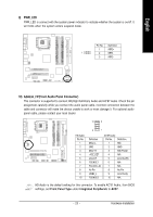
English 9) PWR_LED PWR_LED is connect with the system power indicator to indicate whether the system is on/off. It will blink when the system enters suspend mode. Pin No. Definition 1 MPD+ 1 2 MPD- 3 MPD- 10) AZALIA_FP(Front Audio Panel Connector) This connector is supported to connect HD(High Definition) Audio and AC'97 Audio. Check the pin assignment carefully while you connect the audio panel cable, incorrect connection between the cable and connector will make the device unable to work or even damage it. For optional audio panel cable, please contact your local dealer. 10 9 HD Audio: Pin No. 1 2 3 4 5 6 7 8 9 10 2 1 Definition MIC2_L GND MIC2_R -ACZ_DET Line2_R FSENSE1 FAUOIO_JD No Pin LINE2_L FSENSE2 AC'97 Audio: Pin No. Definition 1 MIC 2 GND 3 MIC Power 4 N/A 5 Line Out (R) 6 N/A 7 N/A 8 No Pin 9 Line Out (L) 10 N/A HD Audio is the default setting for this connector. To enable AC'97 Audio, from BIOS settings, set Front Panel Type under Integrated Peripherals to AC97. - 23 - Hardware Installation
-
 1
1 -
2
-
3
-
4
-
5
-
6
-
7
-
8
-
9
-
10
-
11
-
12
-
13
-
14
-
15
-
16
-
17
-
 18
18 -
 19
19 -
 20
20 -
 21
21 -
 22
22 -
 23
23 -
 24
24 -
 25
25 -
 26
26 -
 27
27 -
 28
28 -
29
-
30
-
31
-
32
-
33
-
34
-
35
-
36
-
37
-
38
-
39
-
40
-
41
-
42
-
43
-
44
-
45
-
46
-
47
-
48
-
49
-
50
-
51
-
52
-
53
-
54
-
55
-
56
-
57
-
58
-
59
-
60
-
61
-
62
-
63
-
64
-
65
-
66
-
67
-
68
-
69
-
70
-
71
-
72
-
73
-
74
-
75
-
76
-
77
-
78
-
79
-
80
 |
 |
