Gigabyte GA-8I945GMBX Manual
Gigabyte GA-8I945GMBX Manual
 |
View all Gigabyte GA-8I945GMBX manuals
Add to My Manuals
Save this manual to your list of manuals |
Gigabyte GA-8I945GMBX manual content summary:
- Gigabyte GA-8I945GMBX | Manual - Page 1
GA-8I945GMBX Intel® Pentium® D / Pentium® 4 LGA775 Processor Motherboard User's Manual Rev. 1002 12ME-8I945GMBX-1002R * The WEEE marking on the product indicates this product must not be disposed of with user's other household waste and must be handed over - Gigabyte GA-8I945GMBX | Manual - Page 2
Motherboard GA-8I945GMBX Aug. 5, 2005 Motherboard GA-8I945GMBX Aug. 5, 2005 - Gigabyte GA-8I945GMBX | Manual - Page 3
. „ For detailed product information and specifications, please carefully read the "Product User Manual". „ For detailed information related to Gigabyte's unique features, please go to "Technology Guide" section on Gigabyte's website to read or download the information you need. For more product - Gigabyte GA-8I945GMBX | Manual - Page 4
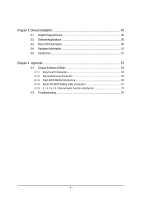
Table of Contents GA-8I945GMBX Motherboard Layout 6 Block Diagram ...7 Chapter 1 Hardware Installation 9 1-1 Considerations Prior to Installation 9 1-2 Feature Summary 10 1-3 Installation of the CPU and Heatsink 12 1-3-1 Installation of the CPU 12 1-3-2 Installation of the Fan Heatsink 13 1-4 - Gigabyte GA-8I945GMBX | Manual - Page 5
53 4-1-1 EasyTune 5 Introduction 54 4-1-2 Xpress Recovery Introduction 55 4-1-3 Flash BIOS Method Introduction 58 4-1-4 Serial ATA BIOS Setting Utility Introduction 67 4-1-5 2- / 4- / 6- / 8- Channel Audio Function Introduction 74 4-2 Troubleshooting 78 - 5 - - Gigabyte GA-8I945GMBX | Manual - Page 6
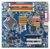
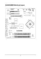
GA-8I945GMBX Motherboard Layout BIOS CI PCI2 IT8712 PCI1 KB_MS Intel Tekoa 82573V PCIE_1 COMB F2_1394 F1_1394 F_PANEL GREEN_USB IDE1 ATX Intel 945G LPT COMA SYS_FAN AUDIO1 AUDIO2 F_AUDIO CD_IN CODEC DDRII1 DDRII2 SPDIF_IO DDRII3 DDRII4 GA-8I945GMBX LGA775 ATX_12V VGA - 6 - - Gigabyte GA-8I945GMBX | Manual - Page 7
Block Diagram VGA PCI-ECLK (100MHz) LGA775 Processor CPUCLK+/-(266/200/133MHz) Host Interface DDRII 667(Note)/533/400MHz DIMM PCI Express x16 Intel 945G GMCH 1 PCI Express x 1 Port PCI-ECLK(100MHz) RJ45 Intel Tekoa 82573V PCI Express x1 Bus PCI Bus TSB43AB23 Intel ICH7R Dual Channel Memory - Gigabyte GA-8I945GMBX | Manual - Page 8
- 8 - - Gigabyte GA-8I945GMBX | Manual - Page 9
, please follow the instructions below: 1. Please turn when handling electronic components (CPU, RAM). 4. Prior information in the provided manual. 3. Before using the any installation steps or have a problem related to the use of the conditions recommended in the user manual. 3. Damage due to - Gigabyte GA-8I945GMBX | Manual - Page 10
(10/100/1000 Mbit) 1 RJ 45 port Supported on the Win 2000/XP operating systems (Note 1) For further CPU support information, please go to GIGABYTE's website. (Note 2) Due to standard PC architecture on the motherboard, you must install an 800/1066MHz FSB processor . GA-8I945GMBX Motherboard - 10 - - Gigabyte GA-8I945GMBX | Manual - Page 11
SPDIF Out connection CD In connection Supported on the Win 2000/XP operating systems IT8712 System voltage detection CPU / System temperature detection CPU / System fan speed detection CPU / System warning temperature CPU / System fan failure warning CPU / System smart fan control Onboard Intel - Gigabyte GA-8I945GMBX | Manual - Page 12
motherboard supports the CPU. 2. Please take note of the one indented corner of the CPU. If you install the CPU in the wrong direction, the CPU will that might cause damage to the CPU during installation.) GA-8I945GMBX Motherboard - 12 - Fig. 4 Once the CPU is properly inserted, please replace - Gigabyte GA-8I945GMBX | Manual - Page 13
an even layer of thermal paste on the surface of the installed CPU. Fig.2 Install the motherboard in the chassis. Align the fan heatsink to the motherboard and chassis. (For detailed installation instructions, please refer to the user's manual for your fan heatsink.) Fig.4 Finally, please attach - Gigabyte GA-8I945GMBX | Manual - Page 14
If you are unable to insert the module, please switch the direction. The motherboard supports DDR II memory modules, whereby BIOS will automatically detect memory capacity and specifications. Memory modules installation steps when you wish to remove the DIMM module. GA-8I945GMBX Motherboard - 14 - - Gigabyte GA-8I945GMBX | Manual - Page 15
English Dual Channel DDR II Memory Configuration The GA-8I945GMBX supports the Dual Channel Technology. When the Dual Channel Technology is activated, the bandwidth of memory bus will be double the original one. The GA-8I945GMBX includes 4 DIMM sockets, and each Channel has 2 DIMM sockets as - Gigabyte GA-8I945GMBX | Manual - Page 16
your expansion card by following the steps outlined below: 1. Read the related expansion card's instruction document before install the expansion card into the computer. 2. Remove your computer's chassis sure your VGA card is locked by the small white-drawable bar. GA-8I945GMBX Motherboard - 16 - - Gigabyte GA-8I945GMBX | Manual - Page 17
device(s) such as USB keyboard, mouse, scanner, zip, speaker...etc. have a standard USB interface. Also make sure your OS supports USB controller. If your OS does not support USB controller, please contact OS ven dor for possible patch or driver upgrade. For more information please contact your OS - Gigabyte GA-8I945GMBX | Manual - Page 18
6) IDE 7) SATAII0_1 / SATAII2_3 8) PWR_LED 9) BATTERY 10) F_PANEL 11) F_AUDIO 12) CD_IN 13) SPDIF_IO 14) F_USB / GREEN_USB 15) F1_1394 / F2_1394 16) COMB 17) CLR_CMOS 18) CI GA-8I945GMBX Motherboard - 18 - - Gigabyte GA-8I945GMBX | Manual - Page 19
installed. Align the power connector with its proper location on the motherboard and connect tightly. The ATX_12V power connector mainly supplies power to the CPU. If the ATX_12V power connector is not connected, the system will not start. Caution! Please use a power supply that is able to handle - Gigabyte GA-8I945GMBX | Manual - Page 20
and failure. Caution! Please remember to connect the power to the CPU fan to prevent CPU overheating and failure. 1 CPU_FAN 1 SYS_FAN Pin No. 1 2 supported are: 360KB, 720KB, 1.2MB, 1.44MB and 2.88MB. Please connect the red power connector wire to the pin1 position. 2 34 1 33 GA-8I945GMBX Motherboard - Gigabyte GA-8I945GMBX | Manual - Page 21
devices, please set the jumper on one IDE device as Master and the other as Slave (for information on settings, please refer to the instructions located on the IDE device). 2 40 1 39 7) SATAII0_1 / SATAII2_3 (SATA 3Gb/s Connector) SATA 3Gb/s can provide up to 300MB/s transfer rate. Please refer - Gigabyte GA-8I945GMBX | Manual - Page 22
1 MPD+ 1 2 MPD- 3 MPD- 9) BATTERY GA-8I945GMBX Motherboard Danger of explosion if battery is incorrectly replaced. Replace only with the same or equivalent type recommended by the manufacturer. Dispose of used batteries according to the manufacturer's instructions. If you want to erase CMOS - Gigabyte GA-8I945GMBX | Manual - Page 23
English 10) F_PANEL (Front Panel Jumper) Please connect the power LED, PC speaker, reset switch and power switch etc. of your chassis front panel to the F_PANEL connector according to the pin assignment below. IDE Hard Disk Reset Switch Active LED NC RES+ RESHD- HD+ 19 1 20 2 SPEAKSPEAK+ PWPW - Gigabyte GA-8I945GMBX | Manual - Page 24
an AC97 front panel audio module to this connector, please refer to the instructions on Page 74 about the software settings. 12) CD_IN (CD In Connector) Connect CD-ROM or DVD-ROM audio out to the connector. Pin No. Definition 1 1 CD-L 2 GND 3 GND 4 CD-R GA-8I945GMBX Motherboard - 24 - - Gigabyte GA-8I945GMBX | Manual - Page 25
. For optional front USB cable, please contact your local dealer. The GREEN_USB connector provides no standby power when system is off and it does not support USB device to wake up from S3 mode. Users who wish to shut down the standby power (note) for their USB devices during system power - Gigabyte GA-8I945GMBX | Manual - Page 26
. For optional COMB cable, please contact your local dealer. Pin No. Definition 2 10 1 NDCDB- 1 9 2 NSINB 3 NSOUTB 4 NDTRB- 5 GND 6 NDSRB- 7 NRTSB- 8 NCTSB- 9 NRIB- 10 No Pin GA-8I945GMBX Motherboard - 26 - - Gigabyte GA-8I945GMBX | Manual - Page 27
English 17) CLR_CMOS (Clear CMOS) You may clear the CMOS data to its default values by this jumper. To clear CMOS, temporarily short 1-2 pin. Default doesn't include the "Shunter" to prevent from improper use this jumper. Open: Normal 1 Short: Clear CMOS 1 18) CI (Chassis Intrusion, Case Open) - Gigabyte GA-8I945GMBX | Manual - Page 28
English GA-8I945GMBX Motherboard - 28 - - Gigabyte GA-8I945GMBX | Manual - Page 29
BIOS to a disk in the event that BIOS needs to be reset to its original settings. If you wish to upgrade to a new BIOS, either Gigabyte's Q-Flash or @BIOS utility can be used. Q-Flash allows the user to quickly and easily update or backup BIOS without entering the operating system. @BIOS - Gigabyte GA-8I945GMBX | Manual - Page 30
detect Temperature, voltage, fan, speed. „ Frequency/Voltage Control This setup page is control CPU clock and frequency ratio. „ Load Fail-Safe Defaults Fail-Safe Defaults indicates the value of the system parameters which the system would be in safe configuration. GA-8I945GMBX Motherboard - 30 - - Gigabyte GA-8I945GMBX | Manual - Page 31
English „ Load Optimized Defaults Optimized Defaults indicates the value of the system parameters which the system would be in best performance configuration. „ Set Supervisor Password Change, set, or disable password. It allows you to limit access to the system and Setup, or just to Setup. „ Set - Gigabyte GA-8I945GMBX | Manual - Page 32
the system will skip the automatic detection step and allow for faster system start up. • Manual User can manually input the correct settings. Access Mode Use this to set the access mode for the hard precomp Landing Zone Landing zone Sector Number of sectors GA-8I945GMBX Motherboard - 32 - - Gigabyte GA-8I945GMBX | Manual - Page 33
capacity. 2.88M, 3.5" 3.5 inch double-sided drive; 2.88M byte capacity. Floppy 3 Mode Support (for Japan Area) Disabled Normal Floppy Drive. (Default value) Drive A Drive B Both memory located above 1 MB in the CPU's memory address map. Total Memory This item displays the memory size that used. - Gigabyte GA-8I945GMBX | Manual - Page 34
Check # CPU Hyper-Threading Limit CPUID Max. to 3 No-Execute Memory Protect (Note) CPU Enhanced Halt (C1E) (Note) CPU Thermal Monitor 2(TM2) (Note) CPU EIST Function (Note) ASF support On-Chip will show up when you install a processor which supports this function. GA-8I945GMBX Motherboard - 34 - - Gigabyte GA-8I945GMBX | Manual - Page 35
Hyper Threading Feature. Please note that this feature is only working for operating system with multi processors mode supported. (Default value) Disables CPU Hyper Threading. Limit CPUID Max. to 3 Enabled Disabled Limit CPUID Maximum value to 3 when use older OS like NT4. Disables CPUID Limit - Gigabyte GA-8I945GMBX | Manual - Page 36
SATA Port 0/2 Set to SATA Port 1/3 Set to USB Controller USB 2.0 Controller USB Keyboard Support USB Mouse Support Azalia Codec Onboard H/W 1394 Onboard H/W LAN Onboard LAN Boot ROM Onboard Serial Port 1 /Slave, this function will auto set to Ch. 0 Master/Slave. GA-8I945GMBX Motherboard - 36 - - Gigabyte GA-8I945GMBX | Manual - Page 37
) Disabled Disable USB 2.0 controller. USB Keyboard Support Enabled Disabled Enable USB keyboard support. Disable USB keyboard support. (Default value) USB Mouse Support Enabled Enable USB mouse support. Disabled Disable USB mouse support. (Default value) Azalia Codec Auto Auto detect - Gigabyte GA-8I945GMBX | Manual - Page 38
Using Parallel port as ECP & EPP mode. ECP Mode Use DMA 3 Set ECP Mode Use DMA to 3. (Default value) 1 Set ECP Mode Use DMA to 1. GA-8I945GMBX Motherboard - 38 - - Gigabyte GA-8I945GMBX | Manual - Page 39
English 2-4 Power Management Setup CMOS Setup Utility-Copyright (C) 1984-2005 Award Software Power Management Setup ACPI Suspend Type Soft-Off by PWR-BTTN PME Event Wake Up Power On by Ring Resume by Alarm x Date (of Month) Alarm x Time (hh:mm:ss) Alarm Power On by Mouse Power On by Keyboard x KB - Gigabyte GA-8I945GMBX | Manual - Page 40
system always in "On" state. Memory When AC-power back to the system, the system will return to the Last state before AC-power off. GA-8I945GMBX Motherboard - 40 - - Gigabyte GA-8I945GMBX | Manual - Page 41
English 2-5 PnP/PCI Configurations CMOS Setup Utility-Copyright (C) 1984-2005 Award Software PnP/PCI Configurations PCI 1 IRQ Assignment PCI 2 IRQ Assignment [Auto] [Auto] Item Help Menu Level` Device(s) using this INT: KLJI: Move Enter: Select F5: Previous Values PCI 1 IRQ Assignment Auto - Gigabyte GA-8I945GMBX | Manual - Page 42
Monitor CPU temperature at 80oC / 176oF. 90oC / 194oF Disabled Monitor CPU temperature at 90oC / 194oF. Disable this function. (Default value) CPU/SYSTEM FAN Fail Warning Disabled Disable fan warning function. (Default value) Enabled Enable fan warning function. GA-8I945GMBX Motherboard - Gigabyte GA-8I945GMBX | Manual - Page 43
with a 3-pin fan power cable. PWM Set to PWM when you use a CPU fan with a 4-pin fan power cable. Note: In fact, the Voltage option can be used for CPU fans with 3-pin or 4-pin power cables. However, some 4-pin CPU fan power cables are not designed following Intel 4-Wire fans PWM control - Gigabyte GA-8I945GMBX | Manual - Page 44
Multiplier Memory Frequency (Mhz) [16X] [Auto] 533 Item Help Menu Level` Set CPU Ratio if CPU Ratio is unclocked KLJI: Move Enter: Select F5: Previous Values +/-/PU/PD: Value (Note) This item will show up when you install a processor which supports this function. GA-8I945GMBX Motherboard - 44 - - Gigabyte GA-8I945GMBX | Manual - Page 45
English 2-8 Load Fail-Safe Defaults CMOS Setup Utility-Copyright (C) 1984-2005 Award Software ` Standard CMOS Features ` Advanced BIOS Features ` Integrated Peripherals ` Power Management Setup ` PnP/PCI Configurations ` PC Health Status ` Frequency/Voltage Control ESC: Quit F8: Q-Flash Load - Gigabyte GA-8I945GMBX | Manual - Page 46
Setup Menu. If you select "Setup" at "Password Check" in Advance BIOS Features Menu, you will be prompted only when you try to enter Setup. GA-8I945GMBX Motherboard - 46 - - Gigabyte GA-8I945GMBX | Manual - Page 47
English 2-11 Save & Exit Setup CMOS Setup Utility-Copyright (C) 1984-2005 Award Software ` Standard CMOS Features ` Advanced BIOS Features ` Integrated Peripherals ` Power Management Setup ` PnP/PCI Configurations ` PC Health Status ` Frequency/Voltage Control ESC: Quit F8: Q-Flash Load Fail- - Gigabyte GA-8I945GMBX | Manual - Page 48
English GA-8I945GMBX Motherboard - 48 - - Gigabyte GA-8I945GMBX | Manual - Page 49
your CD-ROM drive, the driver CD-title will auto start and show the installation guide. If not, please double click the CD-ROM device icon in "My computer", . For USB2.0 driver support under Windows XP operating system, please use Windows Service Pack. After install Windows Service Pack, it will show - Gigabyte GA-8I945GMBX | Manual - Page 50
Applications This page displays all the tools that Gigabyte developed and some free software, you can choose anyone you want and press "install" to install them. 3-3 Driver CD Information This page lists the contents of software and drivers in this CD-title. GA-8I945GMBX Motherboard - 50 - - Gigabyte GA-8I945GMBX | Manual - Page 51
English 3-4 Hardware Information This page lists all device you have for this motherboard. 3-5 Contact Us Please see the last page for details. - 51 - Drivers Installation - Gigabyte GA-8I945GMBX | Manual - Page 52
English GA-8I945GMBX Motherboard - 52 - - Gigabyte GA-8I945GMBX | Manual - Page 53
4 Appendix 4-1 Unique Software Utilities (Not all model support these Unique Software Utilities, please check your MB features.) setup in order to change system settings such as the CPU system bus, memory timings or to enabled Gigabyte's unique C.I.A. 2 and M.I.B. 2 features. M.I.T.'s integration - Gigabyte GA-8I945GMBX | Manual - Page 54
Easy and Advance Mode Display panel of CPU frequency Shows the current functions status Log on to GIGABYTE website Display EasyTuneTM 5 Help file Quit or Minimize EasyTuneTM 5 software (Note) EasyTune 5 functions may vary depending on different motherboards. GA-8I945GMBX Motherboard - 54 - - Gigabyte GA-8I945GMBX | Manual - Page 55
installation of only one OS 4. Must be used with an IDE hard disk supporting HPA 5. The first partition must be set as the boot partition. When the from CD: Boot from CD: Xpress Recovery V1.0 (C) Copy Right 2003. GIGABYTE Technology CO. , Ltd. 1. Execute Backup Utility 2. Execute Restore Utility - Gigabyte GA-8I945GMBX | Manual - Page 56
08/16/2002-I845GE-6A69YG01C-00 F9 For Xpress Recovery Xpress Recovery V1.0 (C) Copy Right 2003. GIGABYTE Technology CO. , Ltd. 1. Execute Backup Utility 2. Execute Restore Utility 3. Remove Backup Image all required driver and software installations are complete. GA-8I945GMBX Motherboard - 56 - - Gigabyte GA-8I945GMBX | Manual - Page 57
Esc to Exit The backup utility will automatically scan your system and back up data as a backup image in your hard drive. Not all systems support access to Xpress Recovery by pressing the F9 key during computer power on. If this is the case, please use the boot from CD-ROM - Gigabyte GA-8I945GMBX | Manual - Page 58
instructions Gigabyte supporting Q-Flash and Dual BIOS, the Q-Flash utility and Dual BIOS utility are combined in the same screen. This section only deals with how to use Q-Flash utility. In the following sections, we take GA-8KNXP Ultra as the example to guide GA-8I945GMBX Motherboard - 58 - - Gigabyte GA-8I945GMBX | Manual - Page 59
English Entering the Q-FlashTM utility: Step1: To use Q-Flash utility, you must press Del in the boot screen to enter BIOS menu. CMOS Setup Utility-Copyright (C) 1984-2004 Award Software Standard CMOS Features Advanced BIOS Features Integrated Peripherals Power Management Setup PnP/PCI - Gigabyte GA-8I945GMBX | Manual - Page 60
reset your system at this stage!! After BIOS file is read, you'll see a confirmation dialog box asking you "Are you sure to update BIOS?" GA-8I945GMBX Motherboard - 60 - - Gigabyte GA-8I945GMBX | Manual - Page 61
English 3. Press Y button on your keyboard after you are sure to update BIOS. Then it will begin to update BIOS. The progress of updating BIOS will be displayed. Please do not take out the floppy disk when it begins flashing BIOS. 4. Press any keys to return to the Q-Flash menu when the BIOS - Gigabyte GA-8I945GMBX | Manual - Page 62
and exit. Part Two: Updating BIOS with Q-FlashTM Utility on Single-BIOS Motherboards. This part guides users of single-BIOS motherboards how to update BIOS using the Q-FlashTM utility. CMOS Setup Utility Language F10: Save & Exit Setup Time, Date, Hard Disk Type... GA-8I945GMBX Motherboard - 62 - - Gigabyte GA-8I945GMBX | Manual - Page 63
English Exploring the Q-FlashTM utility screen The Q-FlashBIOS utility screen consists of the following key components. Q-Flash Utility V1.30 Flash Type/Size SST 49LF003A 256K Q-FlashTM utility bar Task menu for Q-FlashTM utility Enter : Run Keep DMI Data Enable Update BIOS from Floppy Save - Gigabyte GA-8I945GMBX | Manual - Page 64
-Safe Defaults". See how to Load BIOS Fail-Safe Defaults, please kindly refer to Step 6 to 7 in Part One. Congratulation!! You have updated BIOS successfully!! GA-8I945GMBX Motherboard - 64 - - Gigabyte GA-8I945GMBX | Manual - Page 65
Installing the @BIOS utility Fig 2. Installation complete and run @BIOS Click Start/ All Programs/ Gigabyte/@BIOS Select @BIOS item than click Install Fig 3. The @BIOS utility Fig 4. Select the desired such as: 945GMBX.F2). e. Complete update process following the instruction. - 65 - Appendix - Gigabyte GA-8I945GMBX | Manual - Page 66
. IV. Check out supported motherboard and Flash ROM Gigabyte's website for downloading and updating it according to method II. IV. Please note that any interruption during updating will cause system unbooted. V. Do not use @BIOS and C.O.M. (Corporate Online Management) at the same time. GA-8I945GMBX - Gigabyte GA-8I945GMBX | Manual - Page 67
number of drive members times the capacity of the smallest member. The striping block size can be set from 4KB to 128KB. RAID 0 does not support fault tolerance. RAID 1 (Mirroring) RAID 1 writes duplicate data onto a pair of drives and reads both sets of data in parallel. If one of the mirrored - Gigabyte GA-8I945GMBX | Manual - Page 68
Model 0 ST3120026AS 1 ST3120026AS Serial # 3JT329JX 3JT354CP Size Type/Status(Vol ID) 111.7GB Non-RAIDDisk 111.7GB Non-RAIDDisk [ ]-Select [ESC]-Exit [ENTER]-Select Menu GA-8I945GMBX Motherboard - 68 - - Gigabyte GA-8I945GMBX | Manual - Page 69
English Create RAID Volume Press Enter under Create RAID Volume to set up RAID. Intel(R) Matrix Storage Manager option ROM V5.0.0.1011 ICH7R wRAID5 Copyright(C) 2003-04 Intel Corporation. All Rights Reversed. [ CREATE VOLUME MENU ] Name : RAID Level : Disks : Strip Size : Capacity : - Gigabyte GA-8I945GMBX | Manual - Page 70
is needed to utilize the remaining space. [ ]-Change [TAB]-Next [ESC]-Previous Menu Press Enter to enter Create Volume after setting disk capacity. [ENTER]-Select GA-8I945GMBX Motherboard - 70 - - Gigabyte GA-8I945GMBX | Manual - Page 71
English Press Enter under the Create Volume item. Intel(R) Matrix Storage Manager option ROM V5.0.0.1011 ICH7R wRAID5 Copyright(C) 2003-04 Intel Corporation. All Rights Reversed. [ CREATE VOLUME MENU ] Name : RAID Level : Disks : Strip Size : Capacity : RAID_Volume0 RAID0(Stripe) Select Disks - Gigabyte GA-8I945GMBX | Manual - Page 72
RAID volume, please select the Delete RAID Volume option. Press Enter key and follow the instructions on the screen. Intel(R) Matrix Storage Manager option ROM V5.0.0.1011 ICH7R wRAID5 Copyright(C) 111.7GB Member Disk(0) [ ]-Select [ESC]-Exit [ENTER]-Select Menu GA-8I945GMBX Motherboard - 72 - - Gigabyte GA-8I945GMBX | Manual - Page 73
See the instructions below about how to copy the driver in MS-DOS mode(Note 1). Prepare a startup disk that has CD-ROM support and a For users without a startup disk. Use an alternative system and insert the GIGABYTE motherboard drive CD-ROM. From the CDROM drive (example: D:\) double click the - Gigabyte GA-8I945GMBX | Manual - Page 74
work correctly. HD Audio With multiple built-in high quality digital-to-analog converters (DACs) that support audio output at up to 192 kHz/24-bit quality and multi-streaming applications, HD Audio is the Audio I/O tab. In the upper left list, click 2CH Speaker. GA-8I945GMBX Motherboard - 74 - - Gigabyte GA-8I945GMBX | Manual - Page 75
STEP 3: After a speaker or headphone is plugged into the rear Line Out jack, a small window will pop up and ask you what type of equipment is connected. Choose Headphone or Line Out depending on the device connected and click OK. The 2-channel audio setup is completed. 4 Channel Audio Setup STEP 1 : - Gigabyte GA-8I945GMBX | Manual - Page 76
Manager icon in your system tray (you can also find the icon in Control Panel). Double-click the icon to open the Audio Control Panel. GA-8I945GMBX Motherboard - 76 - - Gigabyte GA-8I945GMBX | Manual - Page 77
: At the Sound Effect menu, users can adjust sound option settings as desired. AC'97 Audio Configuration: To enable the front panel audio connector to support AC97 Audio mode, go to the Audio Control Panel and click the Audio I/O tab. In the ANALOG area, click the Tool icon and then select - Gigabyte GA-8I945GMBX | Manual - Page 78
Troubleshooting Below is a collection of general asked questions. To check general asked questions based on a specific motherboard model, please log on to http://www.gigabyte Clear CMOS steps in the manual. If your board doesn't possible computer problems. However, GA-8I945GMBX Motherboard - 78 - - Gigabyte GA-8I945GMBX | Manual - Page 79
.giga-byte.com U.S.A. G.B.T. INC. TEL: +1-626-854-9338 FAX: +1-626-854-9339 Tech. Support : http://tw.giga-byte.com/TechSupport/ServiceCenter.htm Non-Tech. Support(Sales/Marketing) : http://ggts.gigabyte.com.tw/nontech.asp WEB address : http://www.giga-byte.com Germany G.B.T. TECHNOLOGY TRADING GMBH - Gigabyte GA-8I945GMBX | Manual - Page 80
.gigabyte.cz Romania Representative Office Of GIGA-BYTE Technology Co., Ltd. in Romania Tech. Support : http://tw.giga-byte.com/TechSupport/ServiceCenter.htm Non-Tech. Support(Sales/Marketing) : http://ggts.gigabyte.com.tw/nontech.asp WEB address: http://www.gigabyte.com.ro GA-8I945GMBX Motherboard
-
 1
1 -
 2
2 -
 3
3 -
 4
4 -
 5
5 -
 6
6 -
 7
7 -
8
-
9
-
10
-
11
-
12
-
13
-
14
-
15
-
16
-
17
-
18
-
19
-
20
-
21
-
22
-
23
-
24
-
25
-
26
-
27
-
28
-
29
-
30
-
31
-
32
-
33
-
34
-
35
-
36
-
37
-
38
-
39
-
40
-
41
-
42
-
43
-
44
-
45
-
46
-
47
-
48
-
49
-
50
-
51
-
52
-
53
-
54
-
55
-
56
-
57
-
58
-
59
-
60
-
61
-
62
-
63
-
64
-
65
-
66
-
67
-
68
-
69
-
70
-
71
-
72
-
73
-
74
-
75
-
76
-
77
-
78
-
79
-
80
 |
 |

GA-8I945GMBX
Intel
®
Pentium
®
D / Pentium
®
4 LGA775 Processor Motherboard
User's Manual
Rev. 1002
12ME-8I945GMBX-1002R
*
The WEEE marking on the product indicates this product must not be disposed of with user's other household waste
and must be handed over to a designated collection point for the recycling of waste electrical and electronic equipment!!
*
The WEEE marking applies only in European Union's member states.