Gigabyte GA-8I945PLGE-RH Manual - Page 18
Connectors Introduction - audio
 |
View all Gigabyte GA-8I945PLGE-RH manuals
Add to My Manuals
Save this manual to your list of manuals |
Page 18 highlights
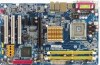
English Center/Subwoofer Speaker Out The default Center/Subwoofer Speaker Out jack. Center/Subwoofer speakers can be connected to Center/Subwoofer Speaker Out jack. Side Speaker Out The default Side Speaker Out jack. Surround side speakers can be connected to Side Speaker Out jack. In addition to the default speakers settings, the ~ audio jacks can be reconfigured to perform different functions via the audio software. Only microphones still MUST be connected to the de- fault Mic In jack ( ) . Please refer to the 2-/4-/6-/8- channel audio setup steps for detailed software configuration information. 1-7 Connectors Introduction 1 3 8 2 4 11 16 17 6 15 10 12 14 5 13 7 9 1) ATX_12V 10) F_PANEL 2) ATX (Power Connector) 11) CD_IN 3) CPU_FAN 12) SPDIF_I 4) SYS_FAN 13) F_USB1/F_USB2 5) FDD 14) RF_ID 6) IDE1 15) CI 7) SATAII0 / SATAII1 / SATAII2 / SATAII3 16) CLR_CMOS 8) F_AUDIO 17) BAT 9) PWR_LED GA-8I945PLGE-RH Motherboard - 18 -
-
 1
1 -
2
-
3
-
4
-
5
-
6
-
7
-
8
-
9
-
10
-
11
-
12
-
 13
13 -
 14
14 -
 15
15 -
 16
16 -
 17
17 -
 18
18 -
 19
19 -
 20
20 -
 21
21 -
 22
22 -
 23
23 -
24
-
25
-
26
-
27
-
28
-
29
-
30
-
31
-
32
-
33
-
34
-
35
-
36
-
37
-
38
-
39
-
40
-
41
-
42
-
43
-
44
-
45
-
46
-
47
-
48
-
49
-
50
-
51
-
52
-
53
-
54
-
55
-
56
-
57
-
58
-
59
-
60
-
61
-
62
-
63
-
64
-
65
-
66
-
67
-
68
-
69
-
70
-
71
-
72
-
73
-
74
-
75
-
76
-
77
-
78
-
79
-
80
 |
 |
