Gigabyte GA-8VM800PMD-775 Manual
Gigabyte GA-8VM800PMD-775 Manual
 |
UPC - 818313002839
View all Gigabyte GA-8VM800PMD-775 manuals
Add to My Manuals
Save this manual to your list of manuals |
Gigabyte GA-8VM800PMD-775 manual content summary:
- Gigabyte GA-8VM800PMD-775 | Manual - Page 1
GA-8VM800PMD-775 Intel® Pentium® 4 LGA775 Processor Motherboard User's Manual Rev. 1001 12ME-VM800PMT-1001R * The WEEE marking on the product indicates this product must not be disposed of with user's other household waste and - Gigabyte GA-8VM800PMD-775 | Manual - Page 2
Motherboard GA-8VM800PMD-775 Nov. 25, 2005 Motherboard GA-8VM800PMD-775 Nov. 25, 2005 - Gigabyte GA-8VM800PMD-775 | Manual - Page 3
following: „ For detailed product information and specifications, please carefully read the "Product User Manual". „ For detailed information related to Gigabyte's unique features, please go to "Technology Guide" section on Gigabyte's website to read or download the information you need. For more - Gigabyte GA-8VM800PMD-775 | Manual - Page 4
Table of Contents GA-8VM800PMD-775 Motherboard Layout 6 Block Diagram ...7 Chapter 1 Hardware Installation 9 1-1 Considerations Prior to Installation 9 1-2 Feature Summary 10 1-3 Installation of the CPU and Heatsink 12 1-3-1 Installation of the CPU 12 1-3-2 Installation of the Heatsink 13 1-4 - Gigabyte GA-8VM800PMD-775 | Manual - Page 5
49 Chapter 4 Appendix 51 4-1 Unique Software Utilities 51 4-1-1 EasyTune 5 Introduction 52 4-1-2 Xpress Recovery Introduction 53 4-1-3 Flash BIOS Method Introduction 56 4-1-4 Configuring SATA Hard Drive(s 65 4-1-5 2 / 4 / 6 Channel Audio Function Introduction 77 4-2 Troubleshooting 83 - 5 - - Gigabyte GA-8VM800PMD-775 | Manual - Page 6
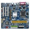
GA-8VM800PMD-775 Motherboard Layout VGA COMA LPT KB_MS LGA775 CPU_FAN DDRII_1 DDRII_2 FDD GA-8VM800PMD-775 ATX_12V ATX USB Winbond W83627 LAN USB AUDIO F_AUDIO BIOS RTL 8100C PCI1 PCI2 CODEC PCI3 CD_IN VIA P4M800 Pro AGP IDE1 IDE2 SYS _FAN VIA SATA1 VT8237R+ SATA0 - Gigabyte GA-8VM800PMD-775 | Manual - Page 7
66MHz) VGA Port 3 PCI RJ45 RTL8100C System Bus 533/800MHz 400/533MHz VIA P4M800 Pro DDR II HCLK (133/200/266MHz) GCLKNB 66MHz 66MHz V_Link 33MHz 14.318MHz 48MHz VIA VT8237R+ 2 Serial ATA LPC BUS Winbond W83627 BIOS Floppy LPT Port AC97 Link PCICLK (33MHz) 6 Channel CODEC 8 USB Ports - Gigabyte GA-8VM800PMD-775 | Manual - Page 8
- 8 - - Gigabyte GA-8VM800PMD-775 | Manual - Page 9
instructions below: 1. Please turn off the computer and unplug its power cord. 2. When handling the motherboard , avoid touching any metal leads or connectors. 3. It is best to wear an electrostatic discharge (ESD) cuff when handling electronic components (CPU, RAM a problem related manual. - Gigabyte GA-8VM800PMD-775 | Manual - Page 10
1 front panel connector Š 1 front audio connector Š 1 CD In connector Š 1 AUX In connector Š 1 COMB connector Š 2 USB 2.0/1.1 connectors for additional 4 USB 2.0/1.1 ports by cables Š 1 SUR_CEN connector Š 1 SPDIF In/Out connector Š 1 power LED connector GA-8VM800PMD-775 Motherboard - 10 - - Gigabyte GA-8VM800PMD-775 | Manual - Page 11
System fan speed detection Š CPU / System fan failure warning Š CPU smart fan control BIOS Š 1 4Mbit flash ROM Š Use of licensed AWARD BIOS Additional Features Š Supports @BIOS Š Supports Download Center Š Supports Q-Flash Š Supports EasyTune (only supports Hardware Monitor function) (Note - Gigabyte GA-8VM800PMD-775 | Manual - Page 12
beyond the proper specifications, please do so according to your hardware specifications including the CPU, graphics card, memory, hard drive, that might cause damage to the CPU during installation.) GA-8VM800PMD-775 Motherboard - 12 - Fig. 4 Once the CPU is properly inserted, please replace the - Gigabyte GA-8VM800PMD-775 | Manual - Page 13
the CPU and make sure the push pins aim to the pin hole on the motherboard.Pressing down the push pins diagonally. Fig. 4 Please make sure the Male and Female push pin are joined closely. (for detailed installation instructions, please refer to the heatsink installation section of the user manual - Gigabyte GA-8VM800PMD-775 | Manual - Page 14
in one direction. Insert the DIMM memory module vertically into the DIMM socket. Then push it down. Fig.2 Close the plastic clip at both edges of the DIMM sockets to lock the DIMM module. Reverse the installation steps when you wish to remove the DIMM module. GA-8VM800PMD-775 Motherboard - 14 - - Gigabyte GA-8VM800PMD-775 | Manual - Page 15
instruction into expansion slot in motherboard. 4. Be sure BIOS. 8. Install related driver from the operating system. Installing a AGP expansion card: Please carefully pull out the small whitedrawable bar at the end of the AGP slot when you try to install/uninstall the VGA card. Please align the VGA - Gigabyte GA-8VM800PMD-775 | Manual - Page 16
USB keyboard, mouse, scanner, zip, speaker...etc. have a standard USB interface. Also make sure your OS supports USB controller. If your OS does not support USB controller, please contact OS vendor for possible patch or driver can be connected to MIC In jack. GA-8VM800PMD-775 Motherboard - 16 - - Gigabyte GA-8VM800PMD-775 | Manual - Page 17
English 1-7 Connectors Introduction 3 2 5 1 6 10 4 7 19 9 11 8 12 14 13 16 17 18 15 1) ATX_12V 2) ATX (Power Connector) 3) CPU_FAN 4) SYS_FAN 5) FDD 6) IDE1 / IDE2 7) SATA0 / SATA1 8) F_PANEL 9) PWR_LED 10) F_AUDIO 11) CD_IN 12) AUX_IN 13) SPDIF_IO 14) SUR_CEN 15) F_USB1 / F_USB2 16) - Gigabyte GA-8VM800PMD-775 | Manual - Page 18
Align the power connector with its proper location on the motherboard and connect tightly. The ATX_12V power connector mainly supplies power to the CPU. If the ATX_12V power connector is not connected, the 15 GND 16 GND 17 GND 18 -5V 19 +5V 20 +5V GA-8VM800PMD-775 Motherboard - 18 - - Gigabyte GA-8VM800PMD-775 | Manual - Page 19
CPU overheating and failure. 1 CPU_FAN 1 SYS_FAN Pin No. 1 2 3 4 Definition GND +12V Sense Speed Control (Only for CPU_FAN) 5) FDD (FDD Connector) The FDD connector is used to connect the FDD cable while the other end of the cable connects to the FDD drive. The types of FDD drives supported - Gigabyte GA-8VM800PMD-775 | Manual - Page 20
for information on settings, please refer to the instructions located on the IDE device). 40 39 2 BIOS setting for the Serial ATA and install the proper driver in order to work properly. Pin No. Definition 1 GND 1 7 2 TXP 3 TXN 4 GND 5 RXN 6 RXP 7 GND GA-8VM800PMD-775 Motherboard - Gigabyte GA-8VM800PMD-775 | Manual - Page 21
English 8) F_PANEL (Front Panel Connector) Please connect the power LED, PC speaker, reset switch and power switch etc. of your chassis front panel to the F_PANEL connector according to the pin assignments below. Message LED/ Power/ Sleep LED Speaker Connector Power Switch MSG+ MSG- PW+ PWSPEAK+ - Gigabyte GA-8VM800PMD-775 | Manual - Page 22
. If you want to use "Front Audio" connector, you must remove the jumpers from pins 5-6, 9-10. 10 9 2 1 Pin No. 1 2 3 4 5 6 7 8 9 10 Definition MIC GND MIC_BIAS POWER FrontAudio(R) Rear Audio (R)/ Return R NC No Pin FrontAudio (L) Rear Audio (L)/ Return L GA-8VM800PMD-775 Motherboard - 22 - - Gigabyte GA-8VM800PMD-775 | Manual - Page 23
(CD IN Connector, black) Connect CD-ROM or DVD-ROM audio out to the connector. Pin No. Definition 1 CD-L 2 GND 1 3 GND 4 CD-R 12) AUX_IN (AUX In Connector, white) Connect other device (such as PCI TV Tunner audio out) to the connector. Pin No. Definition 1 AUX-L 1 2 GND 3 GND - Gigabyte GA-8VM800PMD-775 | Manual - Page 24
(SPDIF In/ Out connector, red) The SPDIF output is capable of providing digital audio to external speakers or compressed AC3 data to an external Dolby Digital Decoder. Use this 15 Pin No. 1 2 3 4 5 6 Definition SUR OUTL SUR OUTR GND No Pin CENTER_OUT BASS_OUT GA-8VM800PMD-775 Motherboard - 24 - - Gigabyte GA-8VM800PMD-775 | Manual - Page 25
cable, incorrect connection between the cable and connector will make the device unable to work or even damage it. For optional front USB cable, please contact your local dealer. 2 10 1 9 Pin No. 1 2 3 4 5 6 7 8 9 10 Definition Power(5V) Power(5V) USB0 DXUSB1 DyUSB0 DX+ USB1 Dy+ GND GND No Pin - Gigabyte GA-8VM800PMD-775 | Manual - Page 26
your system to detect if the chassis cover is removed. You can check the "Case Opened" status in BIOS Setup. Pin No. Definition 1 GND 1 2 Signal 18) CLR_CMOS (Clear CMOS) You may clear the not include a jumper on it. Open: Normal 1 Short: Clear CMOS 1 GA-8VM800PMD-775 Motherboard - 26 - - Gigabyte GA-8VM800PMD-775 | Manual - Page 27
is incorrectly replaced. Replace only with the same or equivalent type recommended by the manufacturer. Dispose of used batteries according to the manufacturer's instructions. If you want to erase CMOS... 1. Turn OFF the computer and unplug the power cord. 2. Take out the battery gently and put it - Gigabyte GA-8VM800PMD-775 | Manual - Page 28
English GA-8VM800PMD-775 Motherboard - 28 - - Gigabyte GA-8VM800PMD-775 | Manual - Page 29
. Q-Flash allows the user to quickly and easily update or backup BIOS without entering the operating system. @BIOS is a Windows-based utility that does not require users to boot to DOS before upgrading BIOS but directly download and update BIOS from the Internet. CONTROL KEYS Move to select item - Gigabyte GA-8VM800PMD-775 | Manual - Page 30
hidden.Please Load Optimized Defaults in the BIOS when somehow the system works not stable as CPU's clock and frequency ratio. „ Load Fail-Safe Defaults Fail-Safe Defaults indicates the value of the system parameters which the system would be in safe configuration. GA-8VM800PMD-775 Motherboard - Gigabyte GA-8VM800PMD-775 | Manual - Page 31
system. „ Save & Exit Setup Save CMOS value settings to CMOS and exit setup. „ Exit Without Saving Abandon all CMOS value changes and exit setup. - 31 - BIOS Setup - Gigabyte GA-8VM800PMD-775 | Manual - Page 32
IDE Channel 3 Master Drive A Floppy 3 Mode Support Halt On Wed, Nov 2 2005 10:40:9 allowed in the month) Base Memory Extended Memory Total Memory 640K 447M 448M 1999 to Sat, determined by the BIOS and is display only Month Manual User can manually GA-8VM800PMD-775 Motherboard - 32 - - Gigabyte GA-8VM800PMD-775 | Manual - Page 33
. Floppy 3 Mode Support (for Japan Area) memory installed on the motherboard. Extended Memory The BIOS determines how much extended memory is present during the POST. This is the amount of memory located above 1 MB in the CPU's memory address map. Total Memory This item displays the memory - Gigabyte GA-8VM800PMD-775 | Manual - Page 34
be denied if the correct password is not entered at the prompt. (Default value) (Note) This item will show up when you install a processor which supports this function. GA-8VM800PMD-775 Motherboard - 34 - - Gigabyte GA-8VM800PMD-775 | Manual - Page 35
system with multi processors mode supported. (Default value) Disables CPU Hyper Threading. Limit CPUID Max. to 3 Enabled Disabled Limit CPUID Maximum value to 3 when use older OS like NT4. Disables CPUID Limit for windows XP. (Default value) No-Execute Memory Protect (Note) Enabled Enables No - Gigabyte GA-8VM800PMD-775 | Manual - Page 36
USB 1.1 controller. (Default value) USB 2.0 Controller Disabled Disable USB 2.0 controller. Enabled Enable USB 2.0 controller. (Default value) USB Keyboard Support Enabled Enable USB keyboard support. Disabled Disable USB keyboard support. (Default value) GA-8VM800PMD-775 Motherboard - Gigabyte GA-8VM800PMD-775 | Manual - Page 37
English USB Mouse Support Enabled Enable USB mouse support. Disabled Disable USB mouse support. (Default value) Onboard H/W LAN Enabled USB storage detect Enabled Disabled Enable USB storage detect function. (Default value) Disable this function. Onboard Serial Port 1 Auto BIOS will - Gigabyte GA-8VM800PMD-775 | Manual - Page 38
) Set ACPI suspend type to S3/STR(Suspend To RAM). USB Device Wake-Up From S3 Disabled Enabled Disable USB Device Wake-Up from S3. (Default value) Enable USB Device Wake-Up from S3. Soft-Off by PWRBTN button, you can press the key to power on the system. GA-8VM800PMD-775 Motherboard - 38 - - Gigabyte GA-8VM800PMD-775 | Manual - Page 39
to POWER ON system. If Resume by Alarm is Enabled. Date (of Month) Alarm : Everyday, 1~31 Time (hh: mm: ss) Alarm: (0~23) : (0~59) : (0~59) - 39 - BIOS Setup - Gigabyte GA-8VM800PMD-775 | Manual - Page 40
,11,12,14,15 to PCI 2. Auto assign IRQ to PCI 3. (Default value) Set IRQ 3,4,5,7,9,10,11,12,14,15 to PCI 3. F1: General Help GA-8VM800PMD-775 Motherboard - 40 - - Gigabyte GA-8VM800PMD-775 | Manual - Page 41
System Temperature CPU Temperature Current SYS FAN Speed Current CPU FAN Speed SYS FAN Fail Warning CPU FAN Fail Warning CPU Smart FAN CPU Temperature Detect System / CPU temperature automatically. Current SYS / CPU FAN Speed (RPM) Detect System / CPU Fan speed status automatically. System / CPU - Gigabyte GA-8VM800PMD-775 | Manual - Page 42
this function. CPU Host Clock CPU Host Clock Control. (Default value) Enabled Enable CPU Host Clock Control. CPU Clock 133MHz ~ 500MHz Set CPU Clock from 133MHz to 500MHz. (Note) This item will show up when you install a processor which supports this function. GA-8VM800PMD-775 Motherboard - Gigabyte GA-8VM800PMD-775 | Manual - Page 43
set DRAM Clock to 200. If you use a DDR II 533 DRAM module, please set DRAM Clock to 266. AGP OverVoltage Control Auto +0.1V BIOS will automatically detect AGP voltage. (Default value) Set AGP OverVoltage Control to +0.1V. +0.2V Set AGP OverVoltage Control to +0.2V. DIMM OverVoltage Control - Gigabyte GA-8VM800PMD-775 | Manual - Page 44
Copyright (C) 1984-2005 Award Software ` Standard CMOS Features ` Advanced BIOS Features ` Integrated Peripherals ` Power Management Setup ` PnP/PCI field loads the factory defaults for BIOS and Chipset Features which the system automatically detects. GA-8VM800PMD-775 Motherboard - 44 - - Gigabyte GA-8VM800PMD-775 | Manual - Page 45
the system will boot and you can enter Setup freely. The BIOS Setup program allows you to specify two separate passwords: SUPERVISOR PASSWORD and only basic items. If you select "System" at "Password Check" in Advance BIOS Features Menu, you will be prompted for the password every time the system is - Gigabyte GA-8VM800PMD-775 | Manual - Page 46
CMOS Setup Utility-Copyright (C) 1984-2005 Award Software ` Standard CMOS Features ` Advanced BIOS Features ` Integrated Peripherals ` Power Management Setup ` PnP/PCI Configurations ` PC Health saving to RTC CMOS. Type "N" will return to Setup Utility. GA-8VM800PMD-775 Motherboard - 46 - - Gigabyte GA-8VM800PMD-775 | Manual - Page 47
. System will reboot automatically after install the drivers, afterward you can install others application. 1. For USB2.0 driver support under Windows XP operating system, please use Windows Service Pack. After install Windows Service Pack, it will show a question mark "?" in "Universal Serial - Gigabyte GA-8VM800PMD-775 | Manual - Page 48
English 3-2 Software Application This page displays all the tools that Gigabyte developed and some free software. You can click an item to install it. 3-3 Software Information This page lists the contents of software and drivers in this CD-title. GA-8VM800PMD-775 Motherboard - 48 - - Gigabyte GA-8VM800PMD-775 | Manual - Page 49
English 3-4 Hardware Information This page lists all device you have for this motherboard. 3-5 Contact Us Please see the last page for details. - 49 - Drivers Installation - Gigabyte GA-8VM800PMD-775 | Manual - Page 50
English GA-8VM800PMD-775 Motherboard - 50 - - Gigabyte GA-8VM800PMD-775 | Manual - Page 51
model support these BIOS setup in order to change system settings such as the CPU system bus, memory the battery on the motherboard to reset the system back Download Center Download Center allows users to quickly download and update their BIOS as well as the latest drivers for their system. Download - Gigabyte GA-8VM800PMD-775 | Manual - Page 52
Easy and Advance Mode Display panel of CPU frequency Shows the current functions status Log on to GIGABYTE website Display EasyTuneTM 5 Help file Quit or Minimize EasyTuneTM 5 software (Note) EasyTune 5 functions may vary depending on different motherboards. GA-8VM800PMD-775 Motherboard - 52 - - Gigabyte GA-8VM800PMD-775 | Manual - Page 53
installation of only one OS 4. Must be used with an IDE hard disk supporting HPA 5. The first partition must be set as the boot partition. When the the BIOS menu, select "Advanced BIOS Feature" and set to boot from CD-ROM. Insert the provided driver CD into your CD drive, then save and exit the BIOS - Gigabyte GA-8VM800PMD-775 | Manual - Page 54
An Energy Star Ally Copyright (C) 1984-2004, Award Software, Inc. Intel 865PE AGPSet BIOS for 8IPE1000MT F1 Check System Health OK . . . Press DEL to enter SETUP be immediately installed after OS and all required driver and software installations are complete. GA-8VM800PMD-775 Motherboard - 54 - - Gigabyte GA-8VM800PMD-775 | Manual - Page 55
Esc to Exit The backup utility will automatically scan your system and back up data as a backup image in your hard drive. Not all systems support access to Xpress Recovery by pressing the F9 key during computer power on. If this is the case, please use the boot from CD-ROM - Gigabyte GA-8VM800PMD-775 | Manual - Page 56
Primary Master : FUJITSU MPE3170AT ED-03-08 Primary Slave : None Secondary Master : CREATIVEDVD-RM DVD1242E BC101 Secondary Slave : None Press DEL to enter SETUP / Dual BIOS / Q-Flash / F9 For Xpress Recovery 08/07/2003-i875P-6A79BG03C-00 GA-8VM800PMD-775 Motherboard - 56 - - Gigabyte GA-8VM800PMD-775 | Manual - Page 57
Backup Load Default Settings Save Settings to CMOS Q-Flash Utility Load Main BIOS from Floppy Load Backup BIOS from Floppy Save Main BIOS to Floppy Save Backup BIOS to Floppy Enter : Run :Move ESC:Reset F10:Power Off Dual BIOS utility bar Q-FlashTM utility title bar Action bar Task menu for - Gigabyte GA-8VM800PMD-775 | Manual - Page 58
Save Main BIOS to Floppy Save Backup BIOS to Floppy Enter : Run :Move ESC:Reset F10:Power Off Do not turn off power or reset your system at this stage!! After BIOS file is read, you'll see a confirmation dialog box asking you "Are you sure to update BIOS?" GA-8VM800PMD-775 Motherboard - 58 - Gigabyte GA-8VM800PMD-775 | Manual - Page 59
Fab after updating. Award Modular BIOS v6.00PG, An Energy Star Ally Copyright (C) 1984-2003, Award Software, Inc. Intel i875P AGPset BIOS for 8KNXP Ultra Fba Check System Health OK , VCore = 1.5250 Main Processor : Intel Pentium(R) 4 1.6GHz (133x12) Memory Testing - Gigabyte GA-8VM800PMD-775 | Manual - Page 60
save and exit. Part Two: Updating BIOS with Q-FlashTM Utility on Single-BIOS Motherboards. This part guides users of single-BIOS motherboards how to update BIOS using the Q-FlashTM utility. CMOS Language F10: Save & Exit Setup Time, Date, Hard Disk Type... GA-8VM800PMD-775 Motherboard - 60 - - Gigabyte GA-8VM800PMD-775 | Manual - Page 61
Q-FlashTM utility Enter : Run Keep DMI Data Enable Update BIOS from Floppy Save BIOS to Floppy :Move ESC:Reset F10:Power Off Action download one BIOS file to the floppy disk so only one BIOS file, 8GE800.F4, is listed. Please confirm again you have the correct BIOS file for your motherboard - Gigabyte GA-8VM800PMD-775 | Manual - Page 62
03/18/2003-I845GE-6A69YG01C-00 6. Press Del to enter BIOS menu after system reboots and "Load BIOS Fail-Safe Defaults". See how to Load BIOS Fail-Safe Defaults, please kindly refer to Step 6 to 7 in Part One. Congratulation!! You have updated BIOS successfully!! GA-8VM800PMD-775 Motherboard - 62 - - Gigabyte GA-8VM800PMD-775 | Manual - Page 63
c. Select @BIOSTM sever d. Select the exact model name on your motherboard e. System will automatically download and update the BIOS. II. Update BIOS NOT through Internet: a. Do not click "Internet Update" icon b. Click "Update New BIOS" c. Please select "All Files" in dialog box while opening the - Gigabyte GA-8VM800PMD-775 | Manual - Page 64
server, please go onto Gigabyte's web site for downloading and updating it according to method II. IV. Please note that any interruption during updating will cause system unbooted. V. Do not use @BIOS and C.O.M. (Corporate Online Management) at the same time. GA-8VM800PMD-775 Motherboard - 64 - - Gigabyte GA-8VM800PMD-775 | Manual - Page 65
BIOS Setup. (3) Configure RAID set in RAID BIOS.(Note) (4) Make a floppy disk containing the SATA controller driver. (5) Install the SATA controller driver . (b) An empty formatted floppy disk. (c) Windows XP/2000 setup disk. (d) Driver CD for your motherboard. (1) Install SATA hard drive(s) in your - Gigabyte GA-8VM800PMD-775 | Manual - Page 66
: Exit F1: General Help F7: Optimized Defaults The BIOS Setup menus described in this section may not show the exact settings for your motherboard. The actual BIOS Setup menu options you will see shall depend on the motherboard you have and the BIOS version. GA-8VM800PMD-775 Motherboard - 66 - - Gigabyte GA-8VM800PMD-775 | Manual - Page 67
Step 2: Later, select Hard Disk Boot Priority under the Advanced BIOS Features menu. In the Hard Disk Boot Priority submenu, select the model of the SATA hard drive onto which you intent to install Microsoft Windows 2000/XP (Figure 2). CMOS Setup Utility-Copyright (C) 1984-2004 Award Software Hard - Gigabyte GA-8VM800PMD-775 | Manual - Page 68
, Please wait... Press key into User Window! Serial_Ch0 Master : ST3120026AS Serial_Ch1 Master : ST3120026AS Figure 4 Step 2: In the VT8237 SATA RAID BIOS utility screen (Figure 5), you can use the UP Size(GB) Status 111.79 Hdd 111.79 Hdd Figure 5 GA-8VM800PMD-775 Motherboard - 68 - - Gigabyte GA-8VM800PMD-775 | Manual - Page 69
to Figure 6 below will appear. VIA Tech. VT8237 SATA RAID BIOS Ver 2.31 Auto Setup For Performance Array Mode RAID 0 (Striping) and press ENTER. And the RAID mode selection menu will appear (Figure 7). The supported RAID modes include RAID 0 for performance, RAID 1 for data protection, and RAID - Gigabyte GA-8VM800PMD-775 | Manual - Page 70
must decide whether you want the RAID array to be configured automatically or manually. Auto Setup allows BIOS to assign the hard drives and create arrays automatically, but it does not contents in the hard drive will be destroyed after the array creation. GA-8VM800PMD-775 Motherboard - 70 - - Gigabyte GA-8VM800PMD-775 | Manual - Page 71
be deleted and press ENTER. A warning message will show up, press Y to confirm or press N to cancel (Figure 10). VIA Tech. VT8237 SATA RAID BIOS Ver 2.31 Create Array Delete Array Create/Delete Spare Select Boot Array Serial Number View The selected array will be destoried. Are you sure? Continue - Gigabyte GA-8VM800PMD-775 | Manual - Page 72
disk arrays then nothing will be displayed on the screen (Figure 13). VIA Tech. VT8237 SATA RAID BIOS Ver 2.31 Create Array Delete Array Create/Delete Spare Select Boot Array Serial Number View Create a RAID Block Size(GB) 64K Size(GB) 223.58 Figure 13 GA-8VM800PMD-775 Motherboard - 72 - - Gigabyte GA-8VM800PMD-775 | Manual - Page 73
recognized during the Windows setup process. First of all, copy the driver for the SATA controller from the motherboard driver CD-ROM to a floppy disk. See the instructions below about how to copy the driver in MS-DOS mode(Note 1). Prepare a startup disk that has CD-ROM support and a blank formatted - Gigabyte GA-8VM800PMD-775 | Manual - Page 74
, press S. * If you do not have any device support disks from a mass storage device manufacturer, or do not want to specify additional mass storage devices for use with Windows, press ENTER. S=Specify Additional Device ENTER=Continue F3=Exit Figure 17 GA-8VM800PMD-775 Motherboard - 74 - - Gigabyte GA-8VM800PMD-775 | Manual - Page 75
correct SATA driver again from the motherboard driver CD. Step 4: When the screen as shown below appears, press ENTER to continue the SATA driver installation from the floppy disk. The driver installation will be finished in about one minute. Windows Setup Setup will load support for the following - Gigabyte GA-8VM800PMD-775 | Manual - Page 76
Windows XP, press F3. Enter= Continue R=Repair F3=Exit Figure 20 (Note: Each time you add a new hard drive to a RAID array, the RAID driver will have to be installed under Windows once for that hard drive. After that, the driver will not have to be installed.) GA-8VM800PMD-775 Motherboard - Gigabyte GA-8VM800PMD-775 | Manual - Page 77
or earphone to "Line Out." Line Out STEP 2: After installing the audio driver, you'll find a Sound Effect icon on the lower right hand taskbar. Click the icon to select the function. STEP 3: On the AC97 Audio Configuration menu, click the Speaker Configuration tab and select the 2-channel mode - Gigabyte GA-8VM800PMD-775 | Manual - Page 78
output check box. Clear the Only SURROUND-KIT check box and press OK. When the Environment setting is None, the sound would be performed as stereo mode (2-channel output). Please select other settings (ex: Living Room) for 4-channel output. GA-8VM800PMD-775 Motherboard - 78 - Line Out Line In - Gigabyte GA-8VM800PMD-775 | Manual - Page 79
to "Line Out",the rear channels to "Line In", and the Center/Subwoofer channels to "MIC In". MIC In Line Out STEP 2: After installing the audio driver, you'll find a Sound Effect icon on the lower right hand taskbar. Click the icon to select the function. Line In STEP 3: On the AC97 - Gigabyte GA-8VM800PMD-775 | Manual - Page 80
same time. "SURROUND-KIT" is included in the GIGABYTE unique "Audio Combo Kit" as picture. STEP 1: Secure the metal bracket of the"Surround Kit" to the chassis back panel with a screw. STEP 2: Connect the "SURROUND-KIT" cable to the SUR_CEN connector on the M/B. GA-8VM800PMD-775 Motherboard - 80 - - Gigabyte GA-8VM800PMD-775 | Manual - Page 81
panel's "Line Out", the rear channels to SURROUND-KIT's REAR R/L, and the Center/Subwoofer channels to SURROUND-KIT's SUB CENTER. STEP 4: After installing the audio driver, you'll find a Sound Effect icon on the lower right hand taskbar. Click the icon to select the function. STEP 5: On the AC97 - Gigabyte GA-8VM800PMD-775 | Manual - Page 82
Device (Optional Device) A "SPDIF output" connector is available on the motherboard. Cable with rear bracket could link to the "SPDIF output" connector SPDIF device cable to the SPDIF_IO connector on the motherboard. STEP 3: Connect SPDIF to the SPDIF decoder. GA-8VM800PMD-775 Motherboard - 82 - - Gigabyte GA-8VM800PMD-775 | Manual - Page 83
Troubleshooting Below is a collection of general asked questions. To check general asked questions based on a specific motherboard model, please log on to http://www.gigabyte.com.tw Question 1: I cannot see some options that were included in previous BIOS after updating BIOS in the manual. If your - Gigabyte GA-8VM800PMD-775 | Manual - Page 84
English GA-8VM800PMD-775 Motherboard - 84 - - Gigabyte GA-8VM800PMD-775 | Manual - Page 85
- 85 - Appendix English - Gigabyte GA-8VM800PMD-775 | Manual - Page 86
English GA-8VM800PMD-775 Motherboard - 86 - - Gigabyte GA-8VM800PMD-775 | Manual - Page 87
: No.6, Bau Chiang Road, Hsin-Tien, Taipei 231, Taiwan TEL: +886-2-8912-4888 FAX: +886-2-8912-4003 Tech. Support : http://tw.giga-byte.com/TechSupport/ServiceCenter.htm Non-Tech. Support(Sales/Marketing) : http://ggts.gigabyte.com.tw/nontech.asp WEB address (English): http://www.gigabyte.com.tw WEB - Gigabyte GA-8VM800PMD-775 | Manual - Page 88
Romania Representative Office Of GIGA-BYTE Technology Co., Ltd. in Romania Tech. Support : http://tw.giga-byte.com/TechSupport/ServiceCenter.htm Non-Tech. Support(Sales/Marketing) : http://ggts.gigabyte.com.tw/nontech.asp WEB address: http://www.gigabyte.com.ro GA-8VM800PMD-775 Motherboard - 88 -
-
 1
1 -
 2
2 -
 3
3 -
 4
4 -
 5
5 -
 6
6 -
 7
7 -
8
-
9
-
10
-
11
-
12
-
13
-
14
-
15
-
16
-
17
-
18
-
19
-
20
-
21
-
22
-
23
-
24
-
25
-
26
-
27
-
28
-
29
-
30
-
31
-
32
-
33
-
34
-
35
-
36
-
37
-
38
-
39
-
40
-
41
-
42
-
43
-
44
-
45
-
46
-
47
-
48
-
49
-
50
-
51
-
52
-
53
-
54
-
55
-
56
-
57
-
58
-
59
-
60
-
61
-
62
-
63
-
64
-
65
-
66
-
67
-
68
-
69
-
70
-
71
-
72
-
73
-
74
-
75
-
76
-
77
-
78
-
79
-
80
-
81
-
82
-
83
-
84
-
85
-
86
-
87
-
88
 |
 |

GA-8VM800PMD-775
Intel
®
Pentium
®
4 LGA775 Processor Motherboard
User's Manual
Rev. 1001
12ME-VM800PMT-1001R
*
The WEEE marking on the product indicates this product must not be disposed of with user's other household waste
and must be handed over to a designated collection point for the recycling of waste electrical and electronic equipment!!
*
The WEEE marking applies only in European Union's member states.